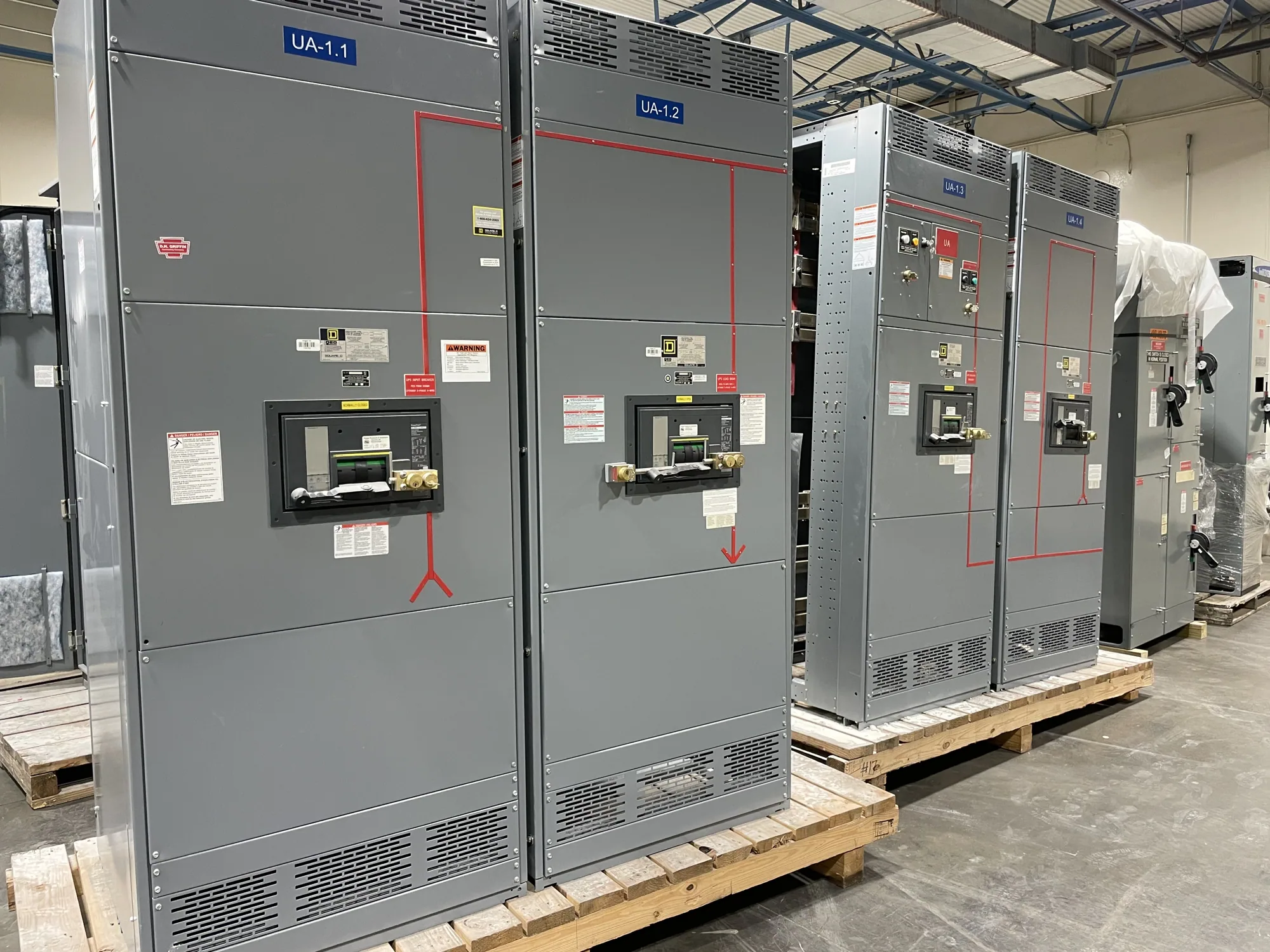
Why ratings matter in a paralleling system
Generator paralleling switchgear connects and controls multiple sources while distributing power to designated loads. Its short-circuit rating is not a single value that can be selected in isolation: the equipment must be specified in relation to the available fault current at the points where sources, bus sections, protective devices and outgoing circuits connect. A sound specification makes those locations and operating conditions clear.
Three related concepts commonly appear in this review. Interrupting capacity concerns a protective device's ability to interrupt a fault under specified conditions. Assembly withstand or short-circuit current ratings address the ability of the equipment assembly to withstand fault effects for the stated conditions and duration. These terms are not interchangeable. The responsible engineer must confirm which device and assembly ratings apply to each part of the proposed lineup.
Map fault current across operating modes
Available fault current can change as the system changes. A utility source, one generator, several generators operating in parallel, or a configuration with a bus tie open or closed may produce different fault-current conditions. The project study should identify credible source combinations and switching states, then evaluate fault current at relevant buses and equipment terminals. Do not assume that a rating suitable for one operating mode covers every configuration.
Generator contribution depends on information such as generator characteristics, system impedance, conductor and transformer data, and the assumed fault condition. The engineer performing the study determines which inputs and calculation methods apply. If values remain preliminary, label them as estimates and identify who will provide verified data and when. The equipment manufacturer needs the design basis, not an unsupported rating chosen from a generic example.
Coordinate devices, buses and protection
Review the rating of each breaker or other interrupting device alongside the assembly's applicable withstand rating. Confirm the location of each device, what it protects, and whether the proposed arrangement depends on a specific protective-device combination or operating condition. Any such limitation should be explicit in the equipment documentation. A lineup rating alone does not establish that every breaker, feeder, or connected component has an adequate rating.
Protection settings and relay functions influence how a fault is detected and cleared; they do not replace adequate interrupting and withstand ratings. In a paralleling application, source control, synchronization, load priority and protective coordination also need to work together. Ask the design team to identify interfaces among relays, generator controls, breakers and supervisory systems, and to distinguish equipment supplied in the lineup from devices or wiring furnished by others.
Consider the real operating sequence
Trade-offs often emerge from the planned source sequence and bus arrangement. A design intended to parallel generators may need review of fault current with multiple units connected, while a standby sequence that transfers sources without paralleling can present different conditions. Tie-breaker positions and load-shedding logic can affect which sources feed a fault. The responsible engineer should document the operating cases that govern the ratings and protection design.
For example, an automotive manufacturing facility might plan to start selected generators, parallel them on a common bus, and restore production loads by priority. This is an illustrative scenario, not a statement about any actual facility; generator sizes, fault-current values, bus layout and operating sequence are unknown. The project engineer would calculate the conditions, confirm the applicable standards and review the proposed equipment configuration before establishing required ratings.
What to provide for equipment review
When requesting a proposal or submittal review, provide the latest one-line diagram, system voltage, source and generator data, transformer information, protective-device schedule, bus arrangement and intended operating sequences. Include the available fault-current study or identify its status, the study's assumptions, and the engineer responsible for final values. Note whether ratings are preliminary, and list any known changes that could affect fault current or equipment configuration.
Also describe required lineup sections, incoming and outgoing connections, control and communications interfaces, space constraints, and the division of work between the switchgear supplier and other contractors. Ask which ratings apply at each section and device, what equipment is excluded from the quoted assembly, and what drawings or calculations must be approved before release. Confirm the specific listing, testing and standards requirements for the actual design rather than assuming universal applicability.
Resolve documentation and delivery details
Submittals should let the project team compare the specified fault-current basis with the proposed equipment configuration. Review drawings, device information, applicable assembly ratings, control interfaces and stated assumptions together. If the study changes, send the revised one-line and calculations for review before finalizing the equipment. A change in source count, generator data, bus ties or protective devices may require a fresh coordination check.
South Carolina Switchgear Builders manufactures new switchgear and switchboards to specification, with US-built equipment, all-American components and nationwide shipping. Short lead times may be available, but availability and actual delivery dates depend on the order and must be confirmed. Provide complete project data early, identify open engineering questions, and coordinate approvals and shipment requirements with the project team. Final ratings and configuration must be confirmed against the approved design and supplied equipment.