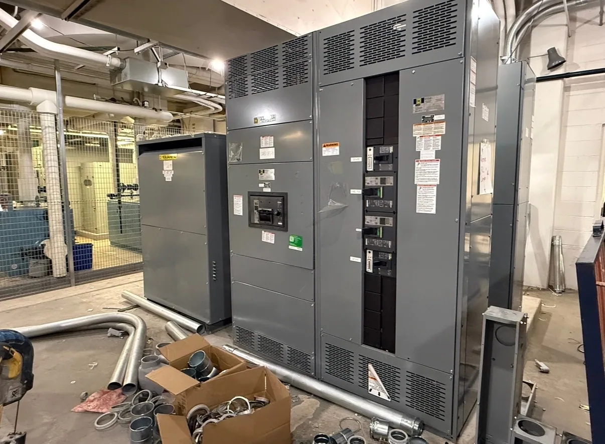
Start with the system the equipment will serve
Generator paralleling switchgear coordinates multiple generator sources and their connection to a distribution system. Its voltage rating is not simply a label chosen from a generator nameplate. The project team must establish the nominal system voltage at the switchgear, the equipment’s applicable maximum voltage rating, the insulation requirements, and how sources and loads connect. These values define the electrical context for the assembly and its interfaces.
Begin with the one-line diagram and the project’s stated system configuration. Identify generator terminals, bus arrangement, utility or alternate-source connections, transformers, and downstream distribution. Confirm whether the paralleling equipment connects directly to the generator voltage or sits on another side of a transformer. Each section and connected device must be considered in its actual application; assumptions based on a facility’s general service voltage can obscure important differences.
Distinguish nominal voltage from equipment rating
Nominal system voltage describes the system’s designated operating level. The equipment rating and its maximum-voltage designation address the voltage conditions for which the specific equipment is designed, as established by the applicable product standard and project specification. Do not treat these terms as interchangeable or select equipment by rounding a nominal value to a familiar catalog label. The responsible engineer should confirm the required rating for the system and installation.
Insulation coordination is part of that review, not a synonym for nominal voltage. The specification may need to address insulation level, clearances, switching duties, grounding, and the conditions expected at the installation. Which requirements apply depends on the equipment design, system grounding, exposure, and governing standards. The manufacturer needs clear project criteria to configure the proposed assembly; the engineer of record remains responsible for establishing and approving system requirements.
Coordinate voltage with paralleling functions
A correct voltage class supports more than the bus and switching devices. Generator controls and protective functions must be specified for the intended sources and system arrangement. The project team should coordinate sensing and control interfaces, synchronization requirements, breaker functions, protective relaying, and any connection to supervisory or facility systems. A voltage mismatch in an interface or instrument-transformer specification can undermine an otherwise sound equipment schedule.
Source sequence and operating modes also matter. Describe which generators may operate together, how sources are added or removed, and whether the equipment interfaces with a utility or another distribution source. Define load priorities and the intended response to changing conditions. These operating details do not determine the voltage rating by themselves, but they help ensure that the proposed paralleling lineup, controls, and protective scheme are specified as one coordinated system.
Review the full system, not an isolated number
Consider a chemical processing facility evaluating new generator paralleling equipment. The site has not yet supplied verified system voltage, generator data, transformer arrangement, grounding method, or operating sequence; those values are unknown and should not be assumed. The project engineer would first map the sources and buses, then identify the applicable equipment class and insulation criteria for each connection point before requesting a configuration.
That review should also examine fault-current calculations, protection coordination, switching duties, and the standards applicable to the specific assembly and installation. These are project-engineering tasks, not values to infer from a general industry label. A qualified engineer should document assumptions, resolve any transformer or bus transitions, and confirm that proposed equipment ratings and control interfaces align with the approved design. Chemical processing alone does not establish a universal voltage or rating.
Information to provide for a specification
- Provide the current one-line diagram, nominal system voltage at each relevant bus, grounding approach, and any transformer connections between generators and loads.
- List generator quantity and electrical data, intended paralleling combinations, source sequence, utility or alternate-source interfaces, and expected operating modes.
- Identify required equipment maximum voltage and insulation criteria, protective functions, control and communications interfaces, and project standards for the responsible engineer to verify.
- Include available fault-current and coordination information, environmental and installation constraints, physical arrangement, and any known future expansion requirements.
- State required submittal content, review milestones, delivery constraints, and any owner or engineer approvals that affect equipment configuration.
Clarify boundaries and coordinate the order
Request confirmation of what the proposed paralleling switchgear includes and excludes. Establish whether generator controls, instrument transformers, protective relays, metering, communications devices, wiring, and external control panels are part of the supplied scope or by others. Confirm ratings, listing applicability, testing, and documentation against the actual proposed design rather than assuming every configuration includes the same features or approvals.
For a quote, send the approved or current design documents and identify open engineering decisions rather than leaving them implicit. South Carolina Switchgear Builders manufactures new equipment to specification, with US-built equipment, all-American components, and nationwide shipping. Availability and actual lead times depend on the order and must be confirmed. Clear voltage criteria, coordinated interfaces, and timely review give the project team a sound basis to evaluate the proposed assembly and move toward an approved equipment submittal.