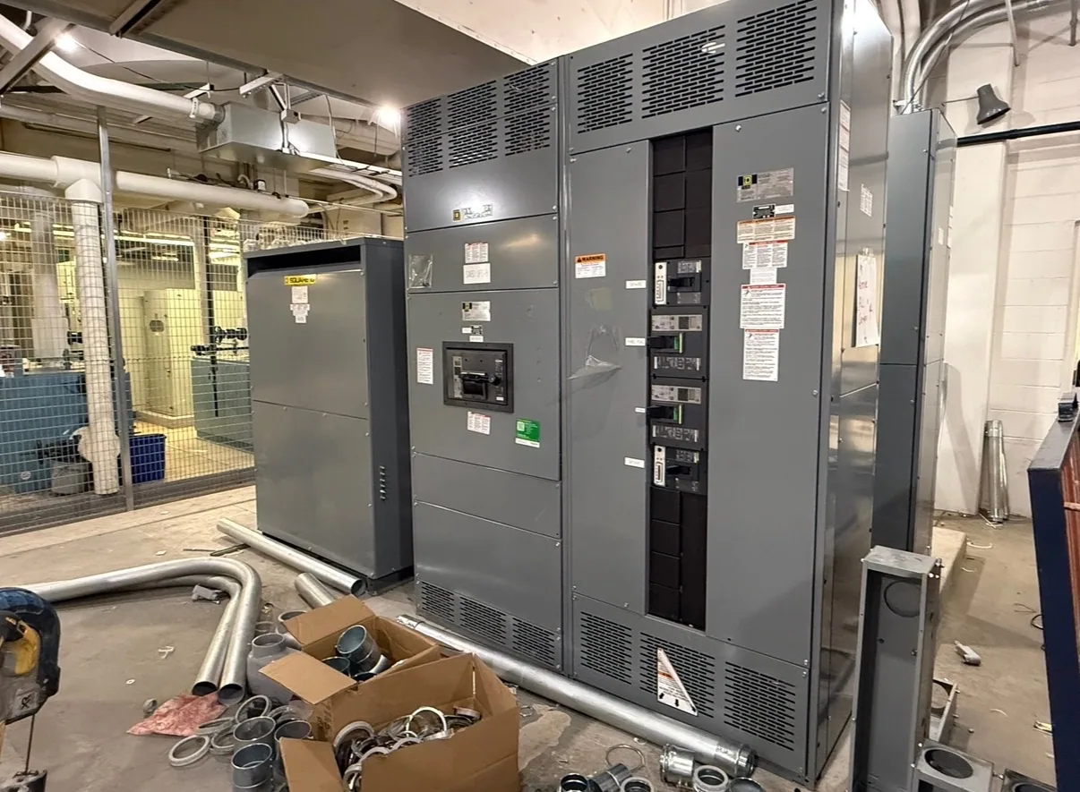
Where grounding and bonding details fit
Indoor switchgear is part of a larger electrical distribution system, so its grounding and bonding provisions cannot be selected in isolation. The design may involve equipment grounding paths, bonded enclosures and structural components, neutral treatment, and a service or separately derived system arrangement. Which provisions apply depends on the project’s system configuration and the responsible engineer’s interpretation of governing requirements.
For equipment installed in a building or electrical room, coordination also includes how the assembly connects to the building grounding and bonding network. The equipment specification should identify the intended interfaces and distinguish equipment furnished with the assembly from conductors, raceways, electrodes, and other work provided elsewhere. Confirm boundaries among the switchgear manufacturer, electrical contractor, engineer, and other project participants.
Start with the actual system arrangement
Provide the one-line diagram and describe the source, service arrangement, voltage class, grounding method, and relevant neutral configuration. Identify whether the equipment is service equipment or part of a downstream distribution arrangement, if known, and show transformers, generators, alternate sources, and transfer equipment that affect the design. Do not assume that a neutral-to-ground connection belongs in every section or that a familiar arrangement applies to this project.
The engineer responsible for the system should determine the required bonding points, grounding conductor paths, and treatment of the neutral in context. Those decisions may depend on the source configuration and applicable code provisions. Ask the equipment supplier to clarify how the specified arrangement is represented in the proposed equipment, and resolve any interface questions before drawings are approved. The supplier’s equipment details do not replace the project engineer’s system design.
Coordinate installation inside the room
Grounding details must be workable alongside the physical layout. Confirm equipment orientation, cable entry and exit, conduit locations, access for conductors, and the intended route to the building grounding network. Room access, door openings, equipment handling path, working clearances, and adjacent systems can influence placement and installation sequence. Provide room drawings and site constraints early enough for the project team to identify conflicts.
Environmental and operating conditions matter as well. Describe indoor temperature ranges, ventilation or cooling assumptions, contaminants, moisture concerns, and other site conditions that the project engineer considers relevant. Heat rejection and enclosure arrangements should be reviewed with the complete equipment specification, not inferred from grounding details alone. The related environmental conditions for indoor switchgear should be documented as project inputs and confirmed for the proposed configuration.
Evaluate trade-offs without guessing
Consider a hypothetical pharmaceutical or biotech facility planning an indoor distribution room. Its project team may need to coordinate critical process loads, standby sources, room access, and an established facility grounding network. The system voltage, fault-current values, neutral arrangement, equipment dimensions, and applicable facility criteria are unknown in this example; they must not be assumed. A qualified engineer should develop and review calculations and applicable standards for the actual project.
Trade-offs can include equipment arrangement, conductor routing, connection access, and coordination with other electrical components. A layout that appears convenient may create installation conflicts or make inspection access difficult. Conversely, space reserved for routing and maintenance can affect room dimensions and equipment placement. Resolve these questions against the project drawings and operating needs rather than applying a generic grounding detail. Confirm which design decisions require engineering approval before they become purchase requirements.
Define scope and documents in the specification
State the required system arrangement and identify grounding and bonding features that the equipment must accommodate. Request drawings that show relevant equipment connections and clearly indicate the limits of supplier scope. Include the one-line diagram, equipment location plan, cable and conduit entry information, room conditions, and project standards or code criteria supplied by the engineer. For submittals, establish who reviews design interfaces and how comments or revisions will be resolved.
Ask the manufacturer to identify assumptions, exclusions, and information still needed to finalize the proposed equipment. Verify ratings, configuration, availability, delivery timing, applicable listing, and testing requirements against the actual specification; none should be presumed from a general description. UL 891 applies only to eligible low-voltage switchboards, and any assembly listing must be verified for the specific design. It does not establish requirements for medium-voltage switchgear.
Buyer checklist and project coordination
- Provide the current one-line diagram, source and service details, voltage class, neutral arrangement, and relevant alternate-source configurations.
- Share room plans, access and working-clearance requirements, conductor routing, cable entry locations, and known installation constraints.
- Identify the project engineer, applicable code and project criteria, required submittal documents, review responsibilities, and approval process.
- Define equipment scope, grounding and bonding interfaces, exclusions, environmental conditions, and any project-specific testing or documentation needs.
Before ordering new indoor switchgear, reconcile the equipment proposal with the engineer-approved system design and the installation plan. Submit complete, consistent project information so open questions can be identified while the configuration is being developed. South Carolina Switchgear Builders manufactures new equipment to specification, with availability and lead times confirmed for each order and nationwide shipping. Final design, ratings, schedule, listing, and delivery details require confirmation against the actual project requirements.