Where coordination fits in an indoor switchgear project
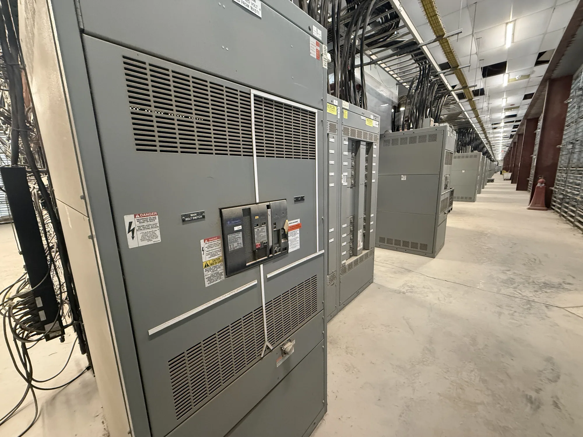
Selective coordination is a project requirement concerning how upstream and downstream overcurrent protective devices respond to fault current. Its purpose and required extent must be established for the particular installation by the responsible electrical engineer. For indoor switchgear, this review connects the electrical distribution design to equipment intended for placement in a building or equipment room; it is not determined by the enclosure location alone.
The equipment specification should identify the distribution arrangement and the protective devices included in the coordination review. Depending on the design, that may involve devices within the switchgear and devices farther downstream. The engineer needs to evaluate their time-current behavior over the project’s specified range and under applicable project requirements. The manufacturer can build new equipment to an approved specification, but coordination conclusions depend on the actual system data and device selections.
Define the required range and design basis
Before requesting equipment, clarify which portions of the system must coordinate, what range of fault conditions the project requires the analysis to cover, and which criteria govern acceptance. These are engineering decisions, not values to assume from a general product description. The basis should also identify the system voltage class, source arrangement, distribution topology, and expected operating configurations that the engineer considers relevant.
Protective-device characteristics, settings, and available fault current can affect whether the specified coordination objective is achievable. Changes to a device family, trip unit, fuse, setting, or upstream source may alter the study. Ask the engineer to identify acceptable alternatives and any limits on adjustments before equipment is finalized. That makes it easier to distinguish a firm design requirement from a preference and to document any tradeoff for owner review.
Balance continuity, protection, and physical constraints
Coordination is not simply a matter of delaying every upstream device. Device response must be assessed against the required protection objectives and the complete system design. A longer operating interval may influence exposure to fault energy or equipment stress; the responsible engineer must assess those consequences using project-specific information. Do not treat a coordination curve by itself as proof that a design is safe, suitable, or compliant.
Indoor installation adds practical constraints that should be addressed alongside the study. Confirm room dimensions, access routes, door openings, working clearances, ventilation or heat-rejection assumptions, cable entry direction, and the planned location of adjacent equipment. These conditions can affect lineup arrangement, section placement, and installation sequencing. The project team should reconcile room drawings and equipment requirements early, while any design-dependent clearances and environmental conditions remain subject to the approved equipment documentation and applicable project review.
Illustrative manufacturing application
Consider an automotive manufacturing facility planning indoor distribution for production areas, support systems, and other loads. The project team may want a fault in one branch to affect as little of the wider distribution system as the specified criteria allow. That is an illustrative objective, not a claim about a particular plant, electrical configuration, fault level, device setting, or guaranteed outcome. Actual values and required coverage remain unknown until the engineer establishes them.
For this scenario, the engineer would need to review the documented source and distribution conditions, selected protective devices, equipment ratings, and operating modes. The design team should also identify loads or processes whose interruption has particular operational consequences, without treating that information as a substitute for electrical analysis. A qualified engineer should perform the required calculations and standards review, then issue the approved device selections, settings, and coordination documentation for the equipment scope.
What to provide for a specification review
A useful request package includes the one-line diagram, available system and source information, voltage class, proposed distribution arrangement, and the engineer’s stated coordination criteria. Include protective-device manufacturer and model information when selected, proposed settings where available, and the study documents or design assumptions that govern the equipment. Mark information that is preliminary so it is not mistaken for an approved value.
- Identify equipment location, indoor environmental assumptions, room drawings, access path, cable entry, and required lineup arrangement.
- List required functions, device types, known ratings, control or metering provisions, and any specified exclusions.
- State the coordination scope, applicable project requirements, responsible engineering contact, and required review documents.
- Flag unresolved source data, alternate operating configurations, and decisions still pending engineering approval.
Do not assume an equipment assembly includes a particular protective device, setting, study, or accessory unless the approved scope says so. Ratings, listing, testing, and standards applicability must be verified for the specific design and supplied equipment. For new indoor switchgear built to specification, availability and actual lead time depend on the order and must be confirmed. Nationwide shipping is available, with delivery planning coordinated against the project schedule.
Coordinate submittals and procurement decisions
Before release, compare the approved one-line diagram and equipment schedule with the proposed lineup and component information. Resolve discrepancies in device identification, ratings, configuration, room fit, and required documentation with the engineer and project team. Establish who reviews and approves submittals, who provides final settings, and how approved changes will be communicated. Clear responsibility helps prevent procurement details from drifting away from the design basis.
South Carolina Switchgear Builders manufactures new switchgear to specification using US-built equipment and all-American components. Share the project requirements and identify which details are final versus pending so the proposed scope can be evaluated accurately. Confirm availability, delivery timing, and design-dependent requirements for the actual order. Installation, testing, and maintenance should be performed by qualified personnel under applicable safety procedures. This coordinated process connects the engineer’s selective-coordination requirements to equipment that can be reviewed against the project’s electrical and physical needs.