How arc-flash safety relates to switchgear
Low-voltage switchgear distributes power and houses protective devices that respond to electrical faults. Arc-flash exposure is not determined by the enclosure alone. It depends on the available fault current, how quickly a protective device operates, equipment construction, system configuration, and the task being performed. A design discussion should therefore connect the proposed assembly to the project’s electrical study and operating procedures.
An arc-flash study evaluates hazards at defined system locations using project-specific information. Its results can inform labels, boundaries, protective equipment selection, and work planning, as determined by qualified professionals and applicable requirements. Incident energy is one study output; it is not a fixed property of a switchgear model. Changes in source conditions, settings, feeder arrangements, or maintenance state may change the results.
Study first, then evaluate design options
Start with a qualified engineer’s analysis of the system and the tasks people are expected to perform. The engineer needs accurate source and distribution data, protective-device characteristics, conductor information, and the proposed equipment arrangement. The study should identify assumptions and boundaries, including which operating configurations were analyzed. If essential inputs remain unknown, document them rather than treating an estimate as a final hazard result.
Design options may affect fault clearing time or where switching and maintenance can be performed, but their suitability depends on the full application. Ask the engineer to evaluate device types, settings, coordination, and any proposed arc-energy-reduction or remote operating approach. Confirm whether an option is available for the specified assembly and whether it changes protection of downstream equipment. No design feature should be described as eliminating arc-flash risk or replacing established work practices.
Ratings, coordination, and maintainability
Interrupting and short-circuit withstand ratings address distinct equipment duties. The protective device must be suitable for the conditions at its point of application, while the assembly must be specified for the applicable short-circuit conditions and duration. The responsible engineer should verify these requirements against the study and system design. Do not select an assembly from an incident-energy target alone or assume that a lower study result establishes adequate equipment ratings.
Protective-device coordination is another project-specific tradeoff. Faster clearing may reduce exposure for some conditions, while settings and selectivity affect continuity of service and the response of upstream or downstream devices. Review the intended operating modes, maintenance access, and consequences of a trip with the design team. Space constraints can also shape device placement and access; resolve those constraints against electrical clearances, cable entry, service needs, and the approved equipment design.
Illustrative manufacturing scenario
Consider an automotive manufacturing facility planning new low-voltage distribution for production loads. At the planning stage, available fault current, final feeder lengths, operating configurations, and protective-device settings may be unknown. These are project inputs to establish, not values to guess. A qualified engineer can model the proposed arrangement, identify study assumptions, and determine what additional information is needed before equipment ratings and settings are finalized.
Production continuity may make coordination and maintenance planning important alongside hazard reduction. The project team can compare operating and maintenance approaches, including whether particular tasks can be performed with equipment in a safer state. The engineer should assess any proposed device or operating feature within the full system model and applicable standards review. The example is illustrative only; actual results, ratings, and suitable configurations depend on verified project conditions.
Information to provide with an equipment specification
Give the manufacturer the required voltage class, system arrangement, source and feeder information available to the project, and the electrical study or its design requirements. Include specified bus and protective-device details, short-circuit duties, enclosure and environmental needs, cable entry preferences, access constraints, and required monitoring or control interfaces. Clearly identify assumptions, items awaiting engineering confirmation, and any owner or engineer preferences that affect the proposed assembly.
Provide the project’s document requirements and identify who will approve drawings, device selections, and final settings. Ask for equipment-specific submittal information needed to verify the proposed configuration against the specification. Confirm which study inputs and protective-device data are supplied by the project team and which details remain subject to engineering review. Listing, testing, ratings, and standards applicability must be checked for the actual design and supplied equipment.
Coordinate equipment and safe work planning
Before release, align the equipment design with the study basis, protective-device coordination, operating modes, and the project’s work-practice program. Confirm that changes to source data, feeder routing, settings, or equipment arrangement are communicated to the responsible engineer for review. The study, labels, and operating documentation should reflect the final installed system as established by the project team; procurement drawings alone cannot settle field conditions.
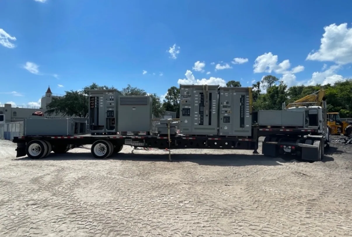
South Carolina Switchgear Builders manufactures new low-voltage switchgear to specification, with US-built equipment, all-American components, and nationwide shipping. Availability and actual lead times depend on the order and must be confirmed. Share the project’s electrical requirements and schedule needs early so the proposed equipment can be reviewed against them. Installation, testing, and maintenance should be planned and performed by qualified personnel under applicable safety procedures.