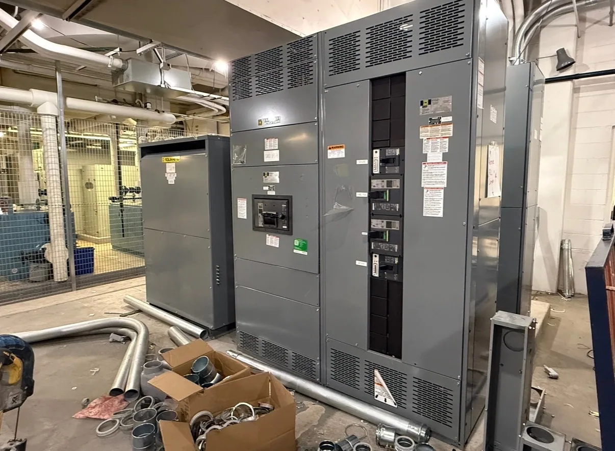
Where busbar design fits in low-voltage switchgear
In low-voltage switchgear, busbars form the conductive paths that connect incoming power, distribution sections and protective devices within the assembly. Their arrangement and construction must suit the project’s electrical requirements and the physical layout of the equipment. Bus material and cross-section matter, but neither can be selected responsibly in isolation from current, fault duty, temperature conditions, enclosure design and the assembly’s ratings.
Busbar design therefore belongs in the equipment specification and engineering review, not just in a dimensional schedule. The complete assembly—including connections, supports, protective devices and enclosure—affects how the bus system performs. Buyers should identify the required configuration and operating conditions, then have the responsible project engineer and manufacturer confirm what can be furnished for the specific design.
Match construction to current and fault duty
Begin with the electrical one-line diagram and the project’s required continuous-current capacity. Identify the incoming source, feeder arrangement, protective devices, intended loads and any planned expansion. These details help establish where current flows and which bus sections or connections must serve particular functions. Do not assume a busbar’s dimensions alone establish its usable capacity; the assembly design and conditions of use must be reviewed together.
Fault duty is a separate, essential input. The available fault current and the required short-circuit or withstand performance must be determined for the installation and coordinated with the protective-device arrangement. Bus supports and bracing are part of the design response to electromechanical forces during a fault. A project team should not infer adequate bracing from appearance or a general product description; confirm the applicable ratings and evidence for the offered assembly and configuration.
Material, cross-section and temperature rise
Specify the bus material and any project preferences, while asking the manufacturer to confirm the proposed construction against the required ratings. Material, cross-section, plating where specified, connection details and surrounding layout interact. A larger conductor is not, by itself, proof that every assembly requirement is met. The design review should consider the full current path, including transitions, joints, device connections and the effects of the enclosure.
Temperature rise is influenced by electrical loading, contact resistance, ambient conditions, ventilation and heat generated by nearby components. State the expected operating environment and any unusual enclosure or room conditions, rather than treating a nominal current value as the entire thermal specification. Ask what design basis and documentation apply to the particular assembly. Required ratings, testing and standards applicability must be verified against the actual equipment; no general statement substitutes for that confirmation.
Joints, expansion and serviceability
Bus joints deserve specific attention because their contact surfaces, fastening method, access and inspection requirements affect both electrical continuity and future maintenance. Identify connections that may need to be reached during planned service, and coordinate joint locations with barriers, cable compartments and protective devices. The design should preserve safe access under the project’s maintenance approach without compromising required separation or the assembly’s specified ratings.
Bus conductors can change dimension as temperature changes, so expansion and mechanical support should be considered in the context of the complete layout and operating range. The project engineer should review transitions between sections, fixed and supported points, and interfaces with connected equipment. Avoid prescribing an unsupported expansion detail before the configuration is known. Clarify whether unusual routing, shipping splits or site connections could affect joint placement and who is responsible for each interface.
Environmental and layout trade-offs
Available space, cable entry direction, room conditions and access requirements influence bus arrangement. A compact layout may affect clearances, heat dissipation, cable bending space and the ability to inspect connections. Provide the equipment footprint and connection constraints early, and identify environmental conditions such as dust, moisture or corrosive exposure when relevant. The responsible engineer should determine which enclosure and construction requirements are appropriate for the actual location.
For example, an automotive manufacturing project might need to coordinate switchgear serving production areas with changing load plans and limited electrical-room space. This is an illustrative scenario only: no load, fault-current, environmental or layout values are assumed. The project team would supply verified study results and operating requirements, then review bus construction, protective-device coordination and maintainability as a complete system rather than selecting bus dimensions from a generic example.
Information to include in a specification
- Provide the one-line diagram, system voltage, source information, required continuous-current capacity and verified available fault-current data.
- Identify incoming and outgoing sections, protective devices, connection locations, cable or bus duct interfaces, and the required equipment arrangement.
- State environmental conditions, space limitations, access expectations, expansion plans and any project-specific material or construction preferences.
- Request confirmation of applicable assembly ratings, listing and standards, along with the design documentation and submittals required for review.
- Clarify shipping splits, field connections, installation responsibilities, testing scope and the qualified personnel responsible for site work.
Review the design before ordering
Before releasing a purchase specification, have the responsible electrical engineer verify system calculations, protection coordination, fault-duty requirements and the applicable codes and standards. Ask the manufacturer to identify exceptions, assumptions and interfaces that need resolution. For eligible low-voltage switchboards, UL 891 may apply, but applicability and assembly listing must be confirmed for the specific design; it is not a blanket claim for every switchgear assembly.
South Carolina Switchgear Builders manufactures new low-voltage equipment to specification, with US-built equipment and all-American components. Availability and actual lead times depend on the order and should be confirmed during project planning. A complete, coordinated specification gives the manufacturer a sound basis to review bus construction, confirm the proposed configuration and identify open questions before equipment details are finalized.