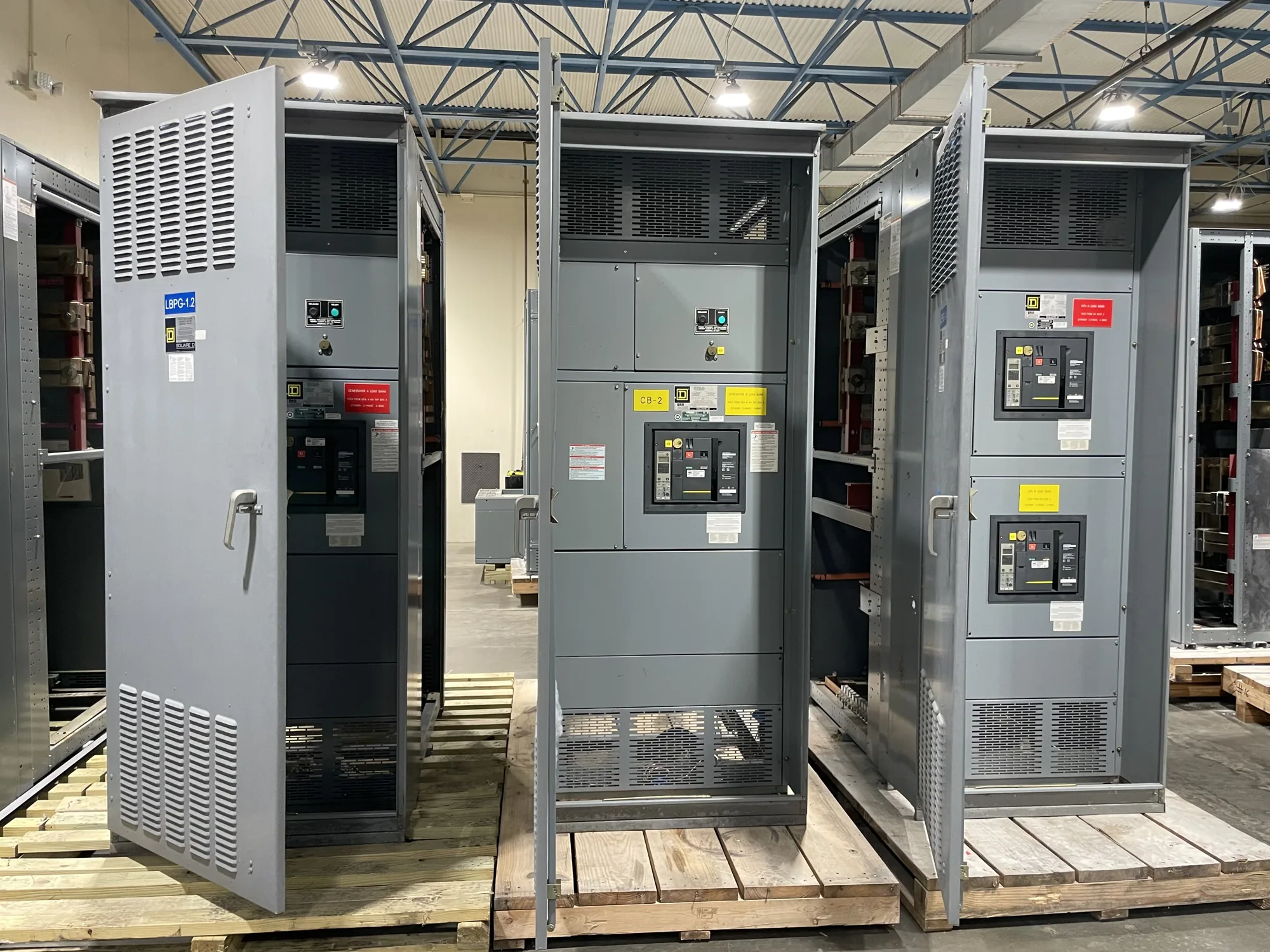
Where continuous current ratings matter
In a low-voltage switchgear assembly, continuous current describes current equipment is designed to carry under specified conditions over time. It is relevant to the assembly’s bus and to individual protective devices, but those ratings are not interchangeable. A switchgear lineup may include a main device, feeder devices, and bus sections with distinct ratings that must be coordinated with the engineered load and the equipment design.
Begin with the load, not a catalog value. The responsible project engineer should establish expected demand using the applicable load information, operating schedules, and design criteria. Nameplate totals alone may not represent simultaneous operation, while future expansion assumptions can affect the required capacity. Document both the calculation basis and the operating scenarios so equipment selection reflects the actual project rather than an unexplained nominal figure.
Coordinate bus and protective-device ratings
The main bus carries current distributed among connected circuits, while feeder conductors and devices serve their respective loads. A protective device’s continuous-current rating, any permitted setting or adjustment, and its application within the assembly require review as a system. A bus rating that appears adequate by itself does not establish that every component or connection is suitable for the specified duty. Confirm each relevant rating on the proposed equipment documents.
Continuous current is only one part of the electrical specification. Short-circuit and interrupting requirements address fault conditions, not ordinary load current, and must be evaluated separately for the installation. Available space and maintainability matter too: the arrangement must accommodate the required devices and provide the clearances and access established by the approved design. A qualified engineer should coordinate these requirements rather than treating a higher current rating as a substitute for a complete design review.
Account for documented operating conditions
Equipment ratings apply in the context of stated design and installation conditions. Ambient temperature, enclosure arrangement, ventilation, elevation, loading pattern, and adjacent heat sources may be relevant depending on the selected assembly and its instructions. Do not assume that a rating remains unchanged under every site condition or that a generic derating factor applies. Identify the actual conditions and ask the manufacturer and project engineer to confirm whether they affect the specified configuration.
Temperature considerations also connect to the layout. Closely grouped devices, cable entry and termination space, and the distribution of load among sections can influence the design review. Where loads vary over a production cycle, provide the expected operating profile rather than only a single peak or average. Any adjustment to equipment selection should be supported by the applicable design documentation and confirmed for the particular assembly.
Illustrative automotive manufacturing scenario
Consider a hypothetical automotive manufacturing project adding production equipment to an existing low-voltage distribution system. No load values, fault-current data, site conditions, or equipment ratings are assumed here. The project team would first identify the new machinery and supporting loads, determine which loads can operate together, and document expected duty cycles. The engineer would then assess the full distribution path, including the proposed switchgear bus and each affected protective device.
That review would also ask whether operating conditions differ from the assumptions behind the selected equipment, whether future phases are part of the scope, and how the new lineup connects with existing systems. The engineer should separately verify applicable fault-duty requirements and protection coordination. This example is not a sizing recommendation: calculations, code and standards review, and confirmation of design-dependent ratings belong to qualified project professionals using the actual project information.
Trade-offs in selecting capacity
Specifying more capacity than the documented load may support planned growth, but it can also affect equipment size, cost, and the space required for installation. Selecting too little may constrain present operation or planned expansion. The right balance depends on the load study, the project’s growth assumptions, the available installation area, and the consequences of later modifications. State the basis for any spare capacity instead of relying on an unstated rule of thumb.
Maintainability and future work should be considered alongside the initial rating. Ask how the lineup will be arranged, how feeder additions might be handled, and whether the specified configuration supports the project’s operational needs. These are design questions, not guarantees of future expandability. The manufacturer can review a defined equipment specification, while the responsible engineer determines how it fits the complete electrical system.
Information to include in the specification
- Provide the system voltage and the required continuous-current ratings for the lineup bus, main device, and each feeder as applicable.
- Include the load calculation or schedule, operating profile, expected simultaneous loads, and documented future-growth assumptions.
- Describe installation conditions that may affect equipment selection, including ambient conditions, enclosure needs, available space, and cable-entry requirements.
- State the required short-circuit and interrupting information separately, along with protection and coordination criteria established by the project engineer.
- Identify the required arrangement, incoming and outgoing connections, metering or control needs, and any project-specific documentation or submittals.
Confirm the proposed equipment before release
Before ordering, compare the proposed equipment documents with the project specification. Confirm that bus and device ratings, operating assumptions, configuration, and identified exclusions match the approved design; ask for clarification wherever a rating or condition is not explicit. Assembly listing, testing, applicable standards, availability, and delivery timing must be confirmed for the specific design and order rather than presumed from a general product description.
South Carolina Switchgear Builders manufactures new low-voltage switchgear to specification, with US-built equipment and all-American components; actual configuration and availability depend on the order. Share the engineer-approved ratings, load information, installation conditions, and submittal requirements for review. Qualified personnel remain responsible for installation, testing, and maintenance under applicable safety procedures. Clear project inputs help align the equipment proposal with the electrical design before procurement proceeds.