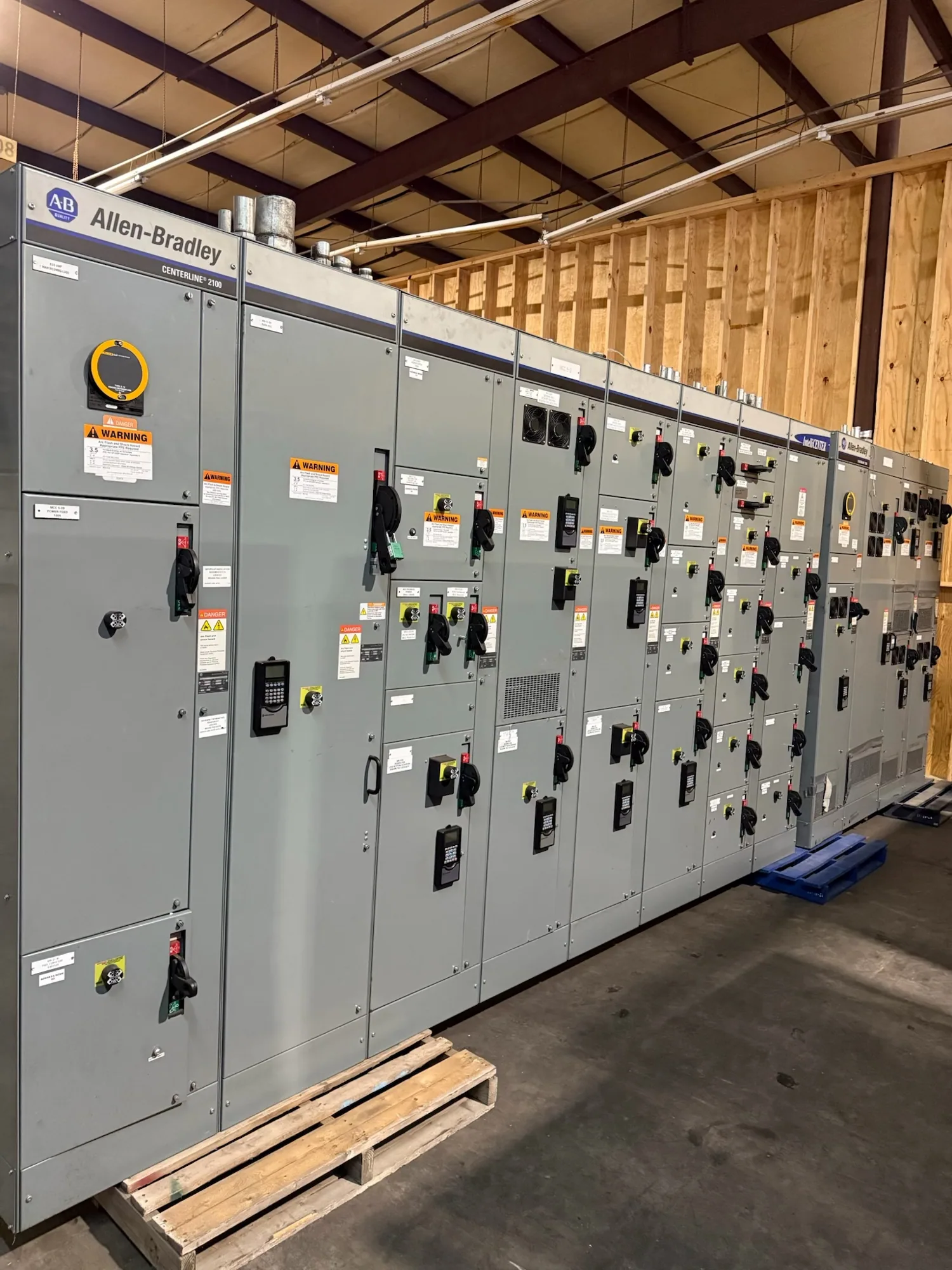
Where protective relays fit in low-voltage switchgear
In low-voltage switchgear, protective relays are part of a coordinated system of sensing, decision-making, and circuit interruption. Depending on the design, relays may receive current or voltage signals, apply configured protection functions, and operate a breaker trip circuit. The relay does not determine whether the entire assembly is suitable by itself: the switchgear, protective devices, sensors, wiring, and application must be evaluated together.
Start by identifying which circuits need protection and what each device is expected to accomplish. A main, tie, feeder, or equipment-specific circuit may have different operating duties and coordination relationships. Some applications use trip units integrated with circuit breakers rather than separate multifunction relays. Define the intended arrangement with the responsible engineer and equipment manufacturer instead of assuming that a particular relay type or feature set fits every low-voltage lineup.
Translate system studies into device requirements
Relay selection should follow the project’s electrical studies and protection philosophy. The engineer needs the system configuration, load and fault information, grounding approach, source characteristics, and relevant upstream and downstream device data. Calculations and review establish which functions and operating ranges are appropriate. A product catalog or a familiar settings example is not a substitute for project-specific analysis.
Confirm the relationship between the selected protective device and the switchgear’s applicable interrupting and withstand ratings. Fault current, clearing behavior, device characteristics, and assembly design all matter; a relay’s nominal features do not establish an assembly rating. The project engineer should verify ratings and application against the actual equipment specification and manufacturer documentation. Any required listing or standard applicability must likewise be confirmed for the specific design.
Match sensing inputs and control power
Specify the sensing inputs needed for the chosen protection functions. Depending on the application, this may include current transformers, voltage transformers, residual or ground-fault sensing, or other defined inputs. Identify ratios, accuracy or performance requirements, polarity and connection details, and any metering or monitoring needs for engineering review. Confirm that the relay’s input ranges and wiring arrangement match the sensors and circuit design; do not infer compatibility from a device name alone.
Control power is another interface to resolve early. State the available source and required operating conditions, and ask how the proposed relay and trip circuit are powered during normal operation and relevant system conditions. The selected arrangement must suit the device documentation and the project’s control scheme. Also specify desired communications, indication, alarm contacts, event records, or remote interfaces where needed, while distinguishing protection functions from optional monitoring features.
Set coordination expectations and operating trade-offs
Settings should be developed by a qualified engineer using the project studies and the specific protective device’s documentation. Time-current behavior, pickup choices, delays, ground-fault treatment, and any adjustable functions can affect selectivity, equipment protection, and continuity of service. More adjustment options are not automatically better: they add configuration and verification work and can create opportunities for incorrect settings if responsibilities are unclear.
Define coordination boundaries across relevant sources and devices, including upstream protection and downstream loads or equipment. Ask which operating modes, ties, or alternate sources the study covers, and how settings will be documented and controlled when the configuration changes. Selective coordination is a system-level objective, not a promise provided by an individual relay. The engineer must evaluate the actual device curves, available fault conditions, and applicable project criteria.
Consider access, space, and maintainability
Relay choice also affects the physical and operational design. Review the proposed device dimensions, panel arrangement, wiring access, display visibility, terminal access, and room for any specified test or isolation provisions. Confirm how technicians will identify circuits and retrieve settings or event information. Maintainability depends on the assembly layout and documented procedures, not simply on the number of functions shown in a relay brochure.
For a new custom switchgear lineup, provide the manufacturer with the project’s required interfaces and documentation expectations before design is finalized. Ask which features are included in the proposed configuration, which are options, and which are outside the equipment scope. Availability, delivery timing, ratings, testing, and standards details depend on the confirmed specification and must be checked for the actual order.
Illustrative manufacturing scenario
Consider an automotive manufacturing facility planning a new low-voltage distribution lineup. The project may need to distinguish production feeders from other loads and account for operating modes that affect coordination. No fault current, load, grounding, device rating, or setting value can be assumed from the facility type. The responsible engineer must establish those values from project information and complete the applicable calculations and standards review.
Useful questions include whether alternate sources or ties change the protection study, which circuits require ground-fault protection, and what monitoring information operators need. Ask how the selected relay or breaker trip unit interfaces with the specified sensors, trip circuit, control power, and communications. These questions help the team compare practical configurations without treating an illustrative use case as a design prescription.
Information to include in a relay specification
- Provide the one-line diagram, system operating modes, available study data, and the circuits and devices included in the equipment scope.
- Identify required protection functions, sensing inputs, control-power source, trip and alarm interfaces, and any communications or event-recording expectations.
- State coordination objectives, applicable project criteria, required ratings, and who is responsible for calculations, settings, review, and approval.
- Request device documentation, proposed interface details, setting-file or schedule expectations, and any specified testing or inspection requirements.
- List exclusions and assumptions explicitly, including field wiring, external sensors, engineering studies, installation, and commissioning when they are not part of the equipment supply.
Before requesting a proposal, resolve open technical questions with the project engineer and identify the documents needed for submittal review. South Carolina Switchgear Builders manufactures new low-voltage switchgear to specification, with US-built equipment and nationwide shipping; configuration and actual lead time require confirmation. A clear relay schedule and interface scope give the manufacturer a sound basis to review the requested assembly and help the project team coordinate design, approval, and delivery planning.