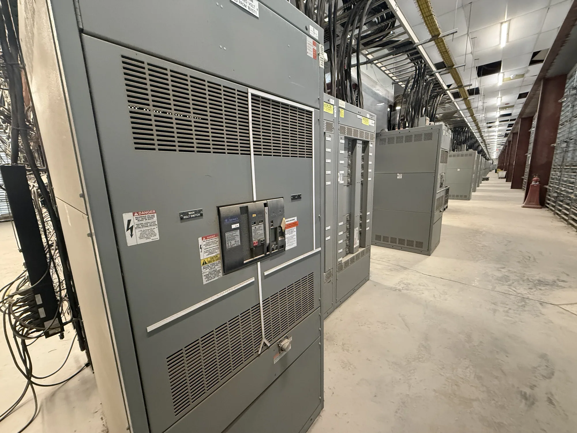
Where coordination fits in a low-voltage assembly
Selective coordination is a system design objective: when a fault occurs, the protective device closest to that fault should operate before upstream devices, to the extent required by the project and across the specified fault-current range. In low-voltage switchgear, this depends on the selected breakers or other protective devices, their settings and characteristics, and their relationship to upstream and downstream equipment. The assembly is one part of that coordinated distribution system.
Coordination is not established simply by choosing a switchgear lineup or matching nominal ratings. Engineers compare device time-current behavior and evaluate the conditions under which devices may respond. The analysis must use applicable project requirements and equipment data. The responsible electrical engineer determines the scope, required degree of coordination, and acceptable exceptions; the manufacturer needs that direction to configure equipment accurately.
Define the required operating range
A useful specification identifies where coordination is required and the range over which it must be demonstrated. That range may depend on available fault current at relevant points, the distribution arrangement, and project criteria. A coordination objective limited to certain downstream circuits differs from one that applies throughout a larger system. Avoid wording that assumes every pair of devices will coordinate under every possible fault condition.
Ask the engineer to identify the governing requirements and the devices included in the study. These may extend beyond the switchgear to upstream sources, transformers, feeders, downstream panels, and connected equipment. Confirm which devices are furnished with the new assembly and which are specified or supplied by others. If the study identifies a conflict or limitation, resolve it through engineering review rather than relying on a general product description.
Balance continuity with protective performance
Allowing a downstream device to clear a fault without tripping an upstream device can preserve service to unaffected loads. However, changing device types, trip settings, or time delays to pursue that outcome can affect other protection objectives. Engineers must consider the full system, including the fault-current range, equipment protection, and applicable requirements. There is no single setting strategy that can be assumed suitable for every low-voltage switchgear application.
Interrupting and withstand ratings are separate, essential checks. The selected equipment and devices must be appropriate for the available fault conditions and specified system characteristics; coordination does not by itself establish those ratings. More separation between device operating curves may also influence clearing time or affect equipment exposure. A qualified engineer should evaluate these tradeoffs using verified device and assembly information before finalizing the design.
Consider maintenance and physical constraints
Protection choices need to work with the way the lineup will be operated and maintained. Discuss access for inspection, device removal or adjustment where applicable, and the project’s maintenance approach. Physical arrangement, compartmentation, cable entry, conductor routing, and available space can constrain the equipment configuration. Share site and installation limits early so the proposed assembly can be reviewed against both the electrical design and the intended layout.
For example, an automotive manufacturing facility may want a fault on one production-area feeder to interrupt fewer unrelated loads. This is an illustrative objective only: fault-current values, device models, settings, process priorities, and required coordination boundaries are unknown. The project engineer would need to establish those inputs, study the upstream and downstream devices, and determine whether the desired behavior is feasible without compromising other protection criteria.
Provide the information needed for review
When requesting new low-voltage switchgear, provide the system voltage and configuration, source and transformer information available to the project team, preliminary one-line diagram, and known fault-current data with its point of reference. Identify downstream loads and distribution equipment, project-specific coordination requirements, and any existing devices that remain part of the system. Label preliminary or unverified values clearly instead of treating estimates as final design inputs.
- State which feeders or device pairs are within the coordination scope and the required operating range.
- Identify device manufacturers and catalog data when already selected, plus any required trip functions or adjustment provisions.
- Provide enclosure, access, cable-entry, footprint, and installation constraints relevant to the lineup.
- List required submittals, study deliverables, review milestones, and responsible parties.
Clarify documentation and equipment boundaries
Ask which information will be included with the equipment submittal and which calculations or system studies are by the project engineer or another designated party. Confirm how proposed protective-device selections and settings will be reviewed against the final one-line diagram and available fault data. Equipment data can support the study, but the purchaser should not assume that selecting or supplying a switchgear assembly automatically completes system coordination or validates the entire installation.
Also document exclusions and dependencies. Upstream devices, downstream equipment, field conductors, final settings, and study revisions may be outside the manufacturer’s equipment scope unless specifically included and confirmed. Requirements for testing, listing, ratings, or standards applicability must be checked against the actual design and supplied assembly; they should not be inferred from a generic coordination statement. Installation, testing, and maintenance are for qualified personnel following applicable safety procedures.
Turn the study requirements into a clear specification
A strong purchase specification ties the coordination objective to identifiable devices, study boundaries, verified project inputs, and review responsibilities. It distinguishes required results from design assumptions and states how unresolved coordination conflicts should be reported. This gives the equipment team a practical basis for proposing a configuration while leaving system calculations and engineering judgments with the responsible project professionals.
South Carolina Switchgear Builders manufactures new low-voltage switchgear to specification, with US-built equipment, all-American components, and nationwide shipping. Availability and actual lead times depend on the order and must be confirmed. For a project review or quotation, provide the current one-line diagram, coordination scope, known device information, physical constraints, and submittal requirements. Confirm the final configuration and documentation against the project engineer’s approved design before release.