Where short-circuit ratings fit
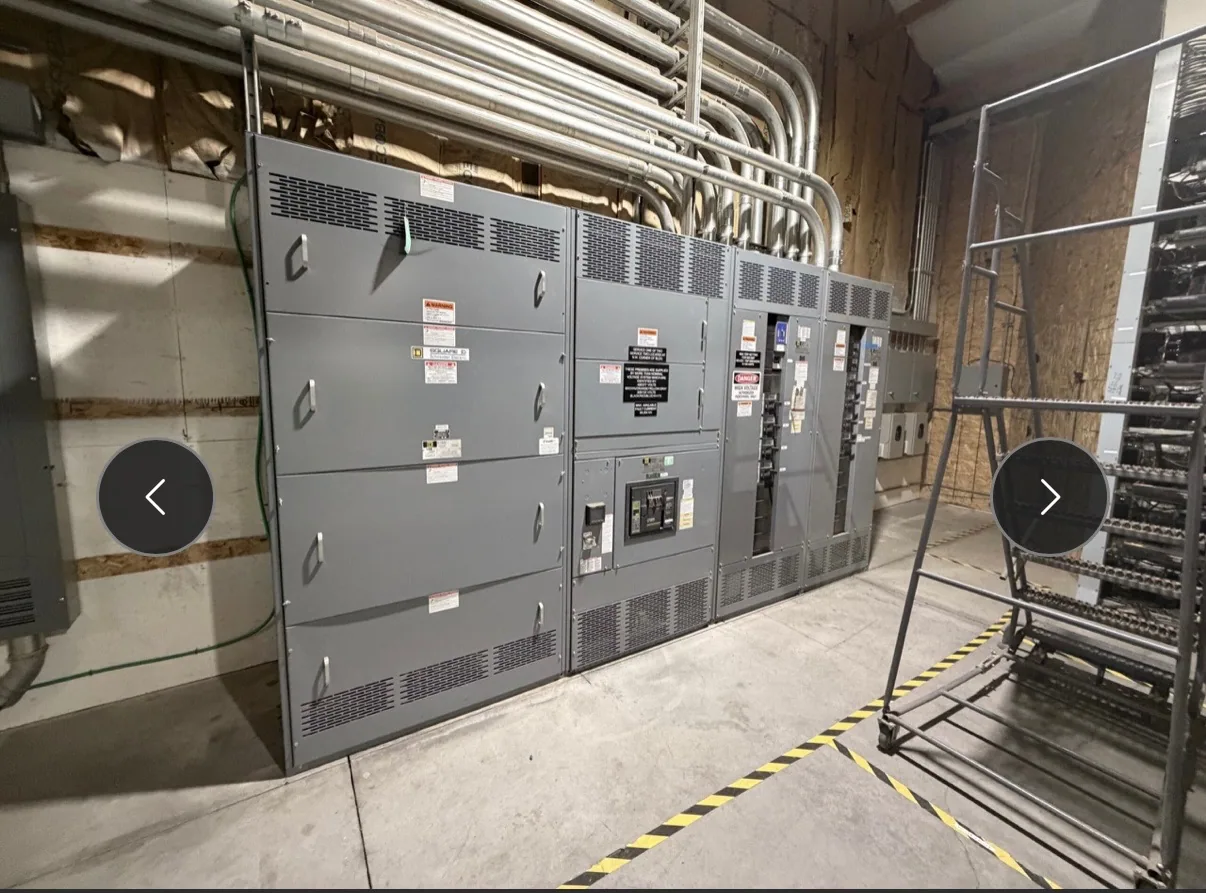
Low-voltage switchgear brings bus, protective devices, and associated components together in an assembly intended for a defined electrical system. Its short-circuit specification cannot be selected from a single number in isolation. The available fault current at the equipment location, the interrupting capability of each protective device, and the assembly’s ability to withstand fault effects are related, but they describe different parts of the application.
Available fault current is a system condition, not an equipment rating. It depends on the source and the electrical path to the point under review, including relevant transformer, conductor, and system configuration data. Protective devices must be suitable for the fault current they may be required to interrupt. The assembly’s applicable short-circuit current or withstand rating must also be evaluated for the specified arrangement and conditions.
Coordinate the system and assembly
Start with the fault-current study or other engineering basis for the proposed installation. The responsible engineer should identify the available fault current at the switchgear line terminals and, where relevant, at downstream points. A value calculated at one location does not automatically describe every bus or device in a distribution system. Source changes, parallel equipment, transformer selection, and feeder impedance can affect the result.
Then compare the system values with the ratings of the specified protective devices and the assembly. Interrupting capacity concerns a device’s ability to interrupt a fault under stated conditions; an assembly withstand or short-circuit rating addresses the assembly’s capability under its specified configuration. A coordinated design must account for the relationship among these ratings rather than assuming that a high device rating alone establishes the suitability of the complete switchgear.
Read rating conditions, not just numbers
Ask how each proposed rating is defined and which conditions apply. Voltage, the protective device type and setting, the tested or evaluated assembly arrangement, and any limitations stated in the manufacturer’s documentation can matter. Verify the exact equipment configuration and the applicable listing or other evidence for the proposed design. Do not transfer a rating from a different lineup, device combination, or operating arrangement without engineering review.
Coordination choices can affect more than fault withstand. Protective-device selection and settings may influence selectivity, interruption, equipment protection, and continuity of operation. These decisions need to fit the project’s protection objectives and the study assumptions. If a design relies on a specific device combination or condition, record it clearly so the specified and supplied configuration can be checked against that basis.
Space, maintenance, and future changes
Switchgear layout and maintainability belong in the same conversation as ratings. The required protective devices, bus arrangement, cable entry, access clearances, and connection points can affect the lineup footprint and service access. Provide the available room dimensions and operating constraints early. If the design may need future feeder additions or source changes, identify them as planning assumptions; do not treat future capacity as established unless it is engineered into the specified assembly.
Higher ratings are not a substitute for a complete application review. They may affect equipment selection, physical arrangement, and cost, while a rating below the project’s documented requirement can make the configuration unsuitable. The project engineer should resolve the necessary design basis and confirm that the requested rating is available for the actual assembly. Availability, listing, and delivery timing depend on the confirmed specification and order.
Illustrative manufacturing scenario
Consider an automotive manufacturing project planning a new low-voltage distribution lineup. The source arrangement, transformer data, feeder lengths, and final equipment location have not yet been provided, so the available fault current is unknown. No specific rating should be assumed from the industry or building type. The engineer first establishes the system model and evaluates fault current at the proposed switchgear and relevant downstream locations.
With that basis, the team can specify protective-device interrupting requirements and the assembly rating, then review coordination goals, access, and operating conditions. If a later project change adds a parallel source or revises a transformer, the study assumptions may change and need review. This example illustrates a process only; it does not establish a rating, design, or standard for any particular facility.
Information to include in a specification
For a useful equipment review, provide the one-line diagram, system voltage, source and transformer information, grounding arrangement, conductor details, and the engineer’s available-fault-current results with calculation locations and assumptions. Identify the required protective-device types and settings, desired coordination approach, lineup arrangement, incoming and outgoing connections, and space constraints. Flag planned operating modes or source configurations that could change the fault-current basis.
- State the required device interrupting ratings and the assembly short-circuit or withstand requirements separately.
- Identify the location and conditions associated with each fault-current value.
- Request documentation showing the proposed device and assembly configuration, applicable limitations, and verified listing status where required.
- Ask the project engineer to identify exclusions, assumptions, and any information still needed before approval.
South Carolina Switchgear Builders manufactures new low-voltage switchgear to specification, with US-built equipment and all-American components. Share the project’s engineering basis and submittal requirements for a configuration review. Specific ratings, listing, testing, availability, and delivery dates must be confirmed against the actual design and order. Qualified personnel should handle installation, testing, and maintenance under applicable safety procedures; engineering review remains essential whenever project conditions or source arrangements change.