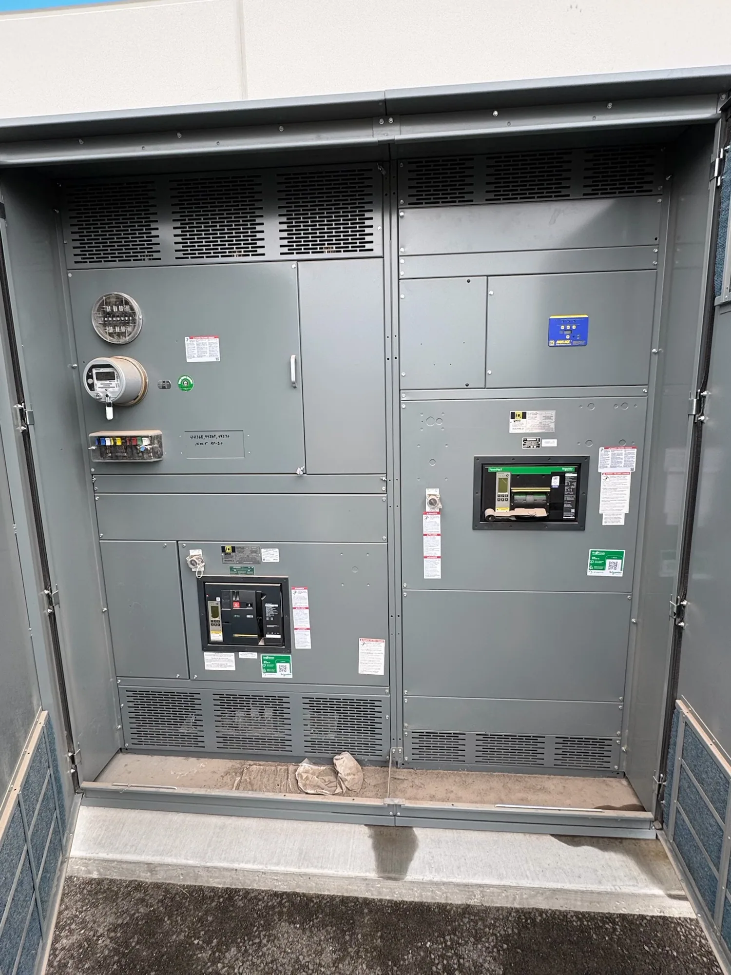
Apply relay protection to the switchgear system
Protective relays in medium-voltage switchgear act on information from sensing devices and, when configured to do so, initiate a trip through the associated control circuit. Selection therefore begins with the system being protected, not with a feature list. Source, transformer, bus, and feeder positions can have different duties, fault exposure, operating arrangements, and coordination relationships.
A relay specification should identify the equipment position and protection purpose, then define required functions and interfaces for that application. A source breaker may need a different protection scheme from a process feeder, but the actual functions cannot be chosen responsibly without the one-line diagram, system study, equipment design, and operating requirements. The project engineer determines the protection approach; the switchgear specification communicates what the assembly must accommodate.
Define sensing inputs and control interfaces
Identify the current and voltage sensing inputs required for each relay and how the project expects those signals to be supplied. Instrument-transformer ratios, accuracy, connection, polarity, grounding, and wiring arrangements must be confirmed against system calculations and the selected device documentation. Do not assume a relay can use any available signal or that a particular sensing arrangement fits every breaker compartment.
Control power is another equipment-specific interface. Specify the intended source and required operating conditions for relay electronics, trip circuits, indication, and communications, as applicable. Confirm the control-power arrangement with the switchgear design and relay manufacturer’s documentation, including what happens when control power is unavailable. The circuit design, trip-coil compatibility, auxiliary contacts, and any required interlocks should be coordinated rather than left to implication.
Specify functions without prescribing unsupported settings
Protection functions should follow an engineering assessment of the system, connected equipment, and operating modes. Depending on the application, the responsible engineer may evaluate overcurrent, ground-fault, voltage, frequency, differential, or other functions. This list is not a recommendation to include every function. Each function needs a defined purpose, suitable input signals, and a documented relationship to the devices upstream and downstream.
Settings are not universal values that can be selected from a catalog description. The engineer establishes them using verified system data, equipment limits, fault and load studies, and the applicable protection objectives. The relay model, firmware or feature set, setting ranges, logic, and trip outputs must then be checked against the proposed scheme. Identify who will develop, review, enter, and document settings, and when those responsibilities occur in the project.
Coordinate relay behavior with system operation
Coordination involves more than choosing a time-current curve. The engineer must consider fault levels, source configurations, transformer characteristics, feeder loading, downstream devices, and any alternate operating modes that affect protection. Selectivity, clearing time, sensitivity, equipment protection, and continuity of service can compete; the design must resolve those trade-offs for the actual installation rather than promise a generic outcome.
For example, an automotive manufacturing project could include a medium-voltage source feeding transformers and production-area feeders. The actual voltage, fault current, transformer data, feeder topology, and operating modes are unknown until supplied and studied. A qualified engineer would use verified project information to assess relay functions and coordination interfaces for each position. This illustrative scenario is not a settings recommendation or evidence of a specific installation.
Account for medium-voltage equipment design
Relay selection must fit the switchgear’s voltage class, insulation design, compartment layout, breaker and trip-circuit interfaces, and specified sensing equipment. Medium-voltage switchgear is not interchangeable with a low-voltage switchboard, and product ratings or construction details should not be inferred from relay features. Ask the manufacturer to confirm that the proposed device, panel arrangement, wiring, and accessories match the project specification.
Also define the intended isolation and maintenance arrangements without treating relay logic as a substitute for safe work practices. Installation, testing, setting changes, and maintenance belong to qualified personnel following applicable procedures. If communications, event records, remote indication, or integration with plant controls are required, state the protocol or interface expectations and identify the system boundary. Compatibility and functionality need confirmation for the actual devices and configuration.
Prepare a complete relay specification package
Provide a current one-line diagram, source and transformer data, voltage class, available fault information, load and operating scenarios, grounding method, and the protection or coordination study basis. Include breaker and compartment requirements, sensing-device data, control-power source, trip-circuit details, desired relay functions, communications needs, and any constraints on footprint or interfaces. Mark unknown values clearly for resolution; do not substitute assumptions for engineering inputs.
- Identify each source, bus, transformer, and feeder position requiring protection.
- State required relay functions and the engineering basis, or request review where functions remain undecided.
- Provide sensing, control-power, trip, indication, and communication requirements.
- Request applicable device documentation, drawings, settings responsibilities, and project-specific exclusions.
- Confirm ratings, listing applicability, testing scope, and delivery requirements against the actual proposed assembly.
During procurement, align the equipment submittal schedule with the engineer’s review of relay data, wiring diagrams, and interface details. Resolve deviations before approval, especially where a device feature, sensing input, or trip arrangement differs from the design intent. Availability and delivery timing depend on the confirmed order and specification. A clear package gives the manufacturer a basis to configure new medium-voltage switchgear while leaving protection calculations and final settings with the responsible qualified engineer.