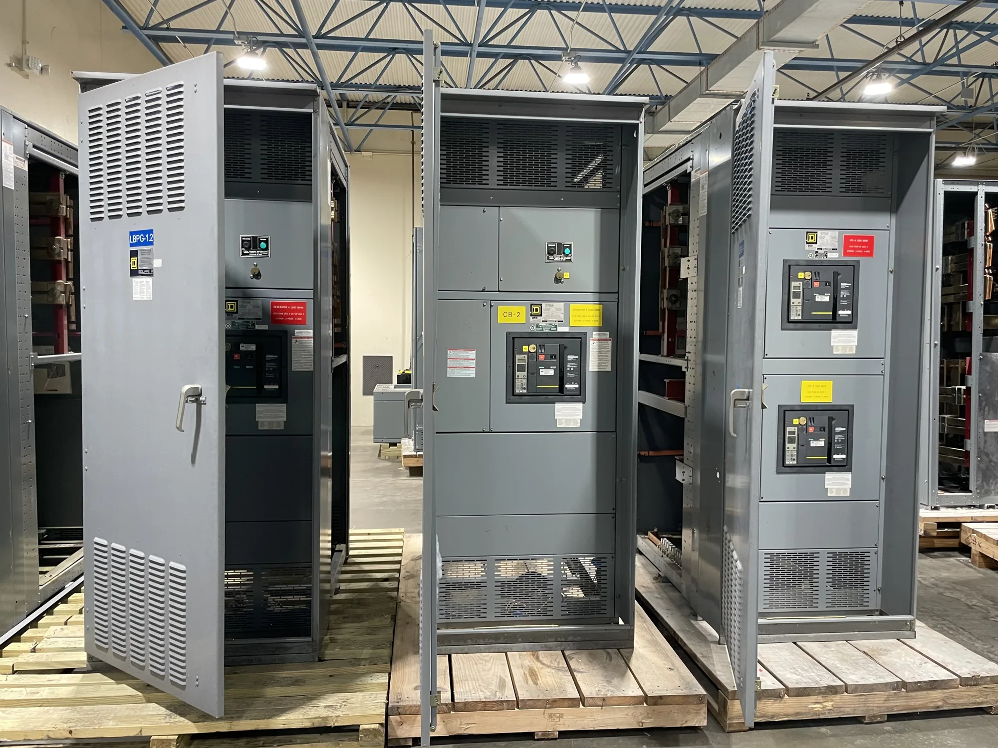
Where coordination fits in a medium-voltage system
In a medium-voltage distribution system, selective coordination is a protection objective: when a fault occurs, the intended downstream protective device should operate before an upstream device, where the design and fault conditions permit. The goal is to limit unnecessary interruption while preserving protection for conductors and equipment. Achieving that behavior is not a feature that can be determined from the switchgear nameplate alone.
Source and feeder arrangements define which devices may respond to a fault and how their operating characteristics relate. The review may include utility or facility sources, incoming protective devices, bus sections, feeder relays, and downstream equipment. The applicable requirements depend on the project, system configuration, and governing code or specification. The responsible electrical engineer should establish the required scope and verify performance for the stated conditions.
Specify the operating range, not just a coordination goal
Coordination depends on more than nominal voltage. Engineers evaluate available fault current, protective-device settings and curves, equipment withstand capability, conductor limits, and the range of operating conditions identified for the project. A result at one assumed fault level does not necessarily establish behavior throughout the required range. Source changes, parallel operation, alternate feeds, or different transformer configurations may affect the analysis.
There can be a real tradeoff between continuity and rapid fault clearing. A longer operating delay may help preserve selectivity with downstream devices, but must remain compatible with equipment withstand limits and the protection strategy. Conversely, faster upstream operation can reduce fault duration but may interrupt more of the distribution system. These choices require coordinated engineering review; no single setting or delay is appropriate for every installation.
Switchgear interfaces that influence the study
For medium-voltage switchgear, identify the voltage class and system arrangement, including incoming and outgoing circuits, bus configuration, and any specified isolation or sectionalizing approach. Insulation and equipment ratings must suit the actual project specification and be confirmed for the proposed assembly. Selective coordination analysis cannot substitute for verifying that the equipment is appropriate for its assigned electrical and operating conditions.
Protective-relay interfaces also need definition. Provide the intended relay functions, current-transformer information, trip circuit requirements, communications or control interfaces, and any owner-specific conventions that affect implementation. Confirm which devices and settings are within the equipment scope and which are supplied or configured by others. Relay selection and settings should follow the approved study and project documents, rather than assumptions made during equipment ordering.
Illustrative manufacturing scenario and tradeoffs
Consider an automotive manufacturing facility with a medium-voltage source feeding process areas through multiple distribution levels. This is an illustrative scenario, not a description of a customer installation. The source arrangement, voltage, fault levels, feeder loads, downstream devices, and required interruption boundaries are unknown. A project engineer would need actual one-line diagrams, utility or source data, device information, and operating modes before evaluating coordination.
The facility might ask whether a fault on one process feeder can be isolated without opening an upstream source device. The answer depends on the specified fault range and the relative characteristics of every relevant protective device. Engineers must also check whether proposed delays remain within equipment and conductor limits and satisfy applicable project requirements. If selectivity cannot be maintained across the entire requested range, the design team should document the limitation and decide which operating conditions or interruption boundaries matter most.
Engineering review and applicable requirements
Ask the responsible qualified engineer to perform or approve the short-circuit and coordination analysis, using confirmed system data and device characteristics. The engineer should identify assumptions, operating cases, required protective-device settings, and any ranges where coordination is not achieved. Applicable codes, owner criteria, and other project requirements must be reviewed for the specific installation; this page does not establish compliance for a particular design.
Review the study against the equipment specification and submittals before release. Confirm that the proposed switchgear configuration provides the stated interfaces and that responsibility for relays, settings, testing, and field integration is clear. Equipment-specific listing, ratings, testing, and availability must be confirmed for the actual design. Installation, testing, and maintenance should be performed only by qualified personnel following applicable safety procedures.
Information to include in a purchase specification
- Provide the project one-line diagram, nominal system voltage, source arrangement, transformer data, and known or required fault-current information.
- Identify incoming and feeder protective devices, relay functions, available device curves, instrument-transformer details, and the intended coordination boundaries.
- State normal and alternate operating configurations, including any planned source transfers, bus ties, or parallel conditions that the study must evaluate.
- Define the required operating range, continuity objectives, applicable project criteria, and who is responsible for the analysis, settings, and approvals.
- Specify switchgear arrangement, isolation needs, interfaces, documentation, and any project-specific equipment requirements; distinguish supplier scope from work by others.
Coordinate the study with the equipment order
Share the approved specification, drawings, study inputs, and submittal requirements early enough for the equipment configuration and protective interfaces to be reviewed together. South Carolina Switchgear Builders manufactures new medium-voltage switchgear to specification, with US-built equipment and all-American components, and ships nationwide. Availability and actual lead times depend on the order and must be confirmed. Clear engineering inputs help the project team resolve scope questions before equipment details are finalized.
Before approving submittals, compare the proposed arrangement and stated interfaces with the latest one-line diagram and protection study. Resolve differences in device scope, ratings, settings responsibility, and operating cases with the project engineer and equipment supplier. This coordinated review gives the buyer a traceable basis for the specified equipment while keeping selective-coordination decisions tied to verified project conditions.