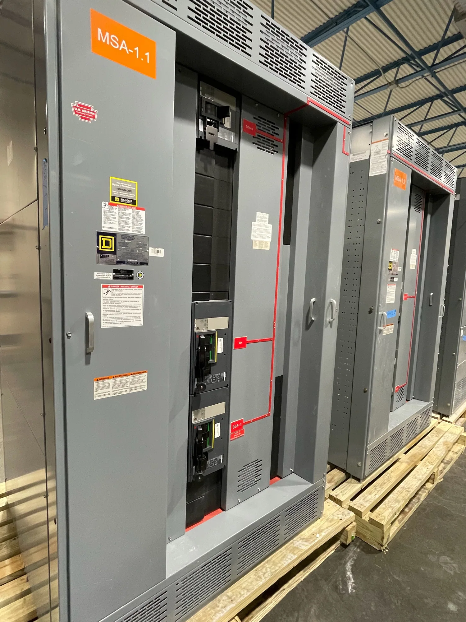
Why ratings matter in a medium-voltage lineup
Medium-voltage switchgear can receive power from a utility connection, transformer, generator, or another source and distribute it through feeder circuits. If a fault occurs, the current contribution and the equipment’s ability to interrupt or withstand that event depend on the system and the specific device involved. Short-circuit ratings therefore belong to the application, not simply to a product name or nominal voltage class.
Three related concepts need to be addressed without treating them as interchangeable: available fault current at a point, the interrupting capability of the switching or protective device, and the short-time withstand or assembly short-circuit rating. The responsible engineer determines which ratings apply to each circuit and operating condition. The equipment specification should identify those requirements clearly so the proposed configuration can be checked against them.
Start with the fault-current study and system boundaries
Available fault current is calculated for defined locations and system configurations. It may vary between the incoming terminals, bus sections, and individual feeder connections. Source characteristics, transformer data, conductor and cable impedance, and the arrangement of ties or parallel sources can affect the result. Switching arrangements also matter: an open tie and a closed tie can represent different operating cases that should not be collapsed into one assumed value.
For procurement, request the study inputs and results at the switchgear connection points, including the operating cases used. Confirm whether the figures are initial, symmetrical, or otherwise expressed according to the governing study method, and have the project engineer identify the required basis. Do not select an interrupting rating or assembly withstand value by guessing from a site voltage or a general rule of thumb.
Coordinate interrupting and withstand capabilities
An interrupting rating addresses a device’s ability to interrupt specified fault current under stated conditions. A withstand rating addresses the assembly’s ability to carry fault current for a defined duration without unacceptable effects, as applicable to its design and rating. The required values and terminology must be verified against the actual equipment specification and applicable standards. One rating does not automatically establish the adequacy of every other component or operating duty.
Coordination includes the protective devices, their settings and interfaces, and the time allowed for fault clearing. The engineer should confirm that the device assigned to clear a fault has a suitable interrupting capability and that connected equipment can withstand the prospective current for the applicable duration. Relay selection and configuration are separate but related decisions; provide the protection philosophy and required interfaces rather than assuming a particular relay or setting is included.
Consider voltage class, insulation, and configuration together
Medium-voltage switchgear is not specified by short-circuit rating alone. State the system voltage class and insulation requirements, then define the lineup arrangement, incoming source, bus configuration, feeder count, and switching functions. Isolation and grounding provisions, instrument transformers, metering, and protective-relay interfaces may affect the design. Each element should be described as a project requirement or confirmed as an offered configuration, not presumed from a broad equipment category.
Higher fault capability can affect equipment selection and the configuration available for a particular application. The project team should weigh the calculated duty against system flexibility, protection coordination, and the required operating arrangement. A rating selected without regard to feeder protection or future operating cases may leave important assumptions unresolved. Conversely, specifying a value without study support can constrain the design unnecessarily, so the engineer should document the basis.
Automotive manufacturing example: define the unknowns
Consider an automotive manufacturing facility planning a new medium-voltage source lineup with feeders to production areas. This example has no assumed voltage, fault-current value, source impedance, or equipment rating. The engineering team would first establish the utility and on-site source data, transformer information, and intended bus and tie operating states. It would then calculate available fault current at the relevant connection points and identify the required device and assembly duties.
Production continuity may make feeder selectivity and the consequences of a fault important design questions, but it does not determine a rating by itself. The project engineer should review the protection approach, clearing times, relay interfaces, and applicable standards for the actual installation. The manufacturer can use the resulting requirements to evaluate a proposed new lineup; it cannot substitute a generic rating description for the project study.
Information to include in the equipment specification
Provide the one-line diagram, nominal system voltage, source and transformer data, fault-study results, and operating cases used to derive them. Identify the point-by-point available fault current and the required interrupting and assembly withstand or short-circuit current ratings, with units, duration, and calculation basis as applicable. Note bus arrangement, incoming and feeder functions, tie operation, protection philosophy, and any required relay, metering, or instrument-transformer interfaces.
Also state enclosure and installation conditions, cable entry and termination expectations, control power needs, documentation requirements, and the applicable project standards. Ask which ratings apply to the complete assembly and which apply to individual devices, and request confirmation of equipment-specific exclusions or assumptions. Listing, testing, ratings, and standards applicability must be checked for the actual design and supplied equipment; no general statement should be read as approval of every configuration.
Review submittals before release
Before releasing a purchase order, have the engineer compare the proposed equipment documents with the final fault study and one-line diagram. Resolve differences in bus sections, feeder duties, source configurations, protective interfaces, and stated ratings. Confirm any design-dependent options, documentation, availability, and delivery dates with the manufacturer; actual lead times depend on the order and must be confirmed. Clear, coordinated requirements help the supplier assess a new lineup against the intended application and give the project team a sound basis for approval.