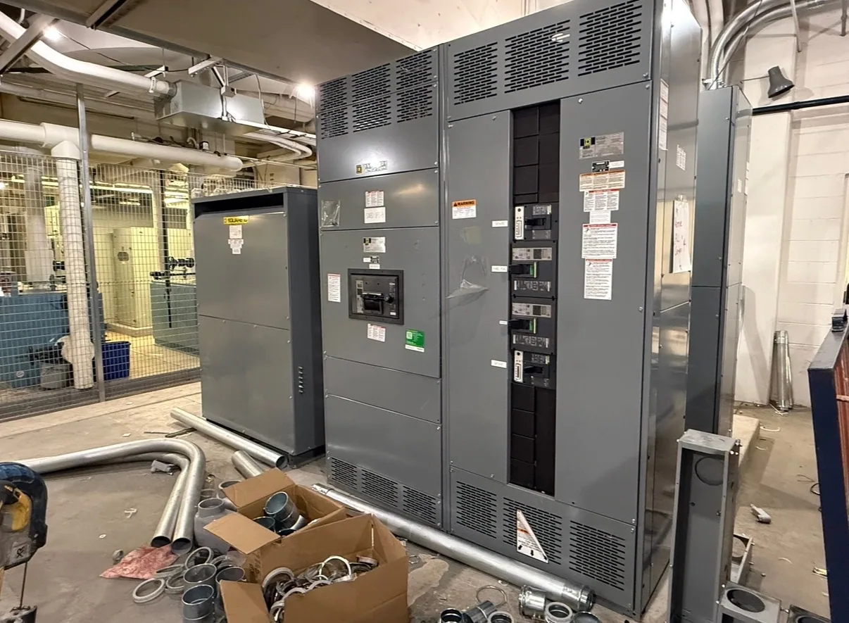
Apply coordination to the specified switchgear system
Selective coordination concerns how protective devices respond to faults at different points in an electrical system. For metal-clad switchgear, this is an application question involving medium-voltage relays, circuit breakers, upstream protection, downstream devices, and the project’s required operating conditions—not a feature that can be confirmed from the enclosure description alone. The responsible engineer must establish the system boundaries and applicable requirements.
The aim is generally to isolate a faulted portion while keeping unaffected portions in service, where the protection design and system conditions permit. Coordination must also preserve adequate protection for conductors and equipment. A setting that delays an upstream device to improve selectivity may affect fault-clearing time elsewhere; the acceptable balance depends on the study, equipment limits, and project criteria. No single timing relationship is suitable for every installation.
Understand device behavior across the system
Time-current behavior compares how quickly protective devices operate at varying current levels. A coordination review may examine relay curves, breaker operating characteristics, current transformers, downstream fuse or breaker data, and upstream utility or facility protection information. The engineer needs the applicable fault-current range and operating scenarios to assess whether device responses remain appropriately ordered across the specified conditions.
Curves alone may not settle the question. The review may need to account for relay settings, breaker clearing characteristics, tolerances, available fault current, equipment withstand limits, and applicable project rules. Ask the project engineer to identify the intended range of coordination and the assumptions used. If required device data or system conditions are unknown, mark them as open inputs rather than treating a preliminary curve comparison as a verified result.
Connect protection choices to metal-clad design
Metal-clad construction organizes medium-voltage components into separate compartments and commonly uses removable circuit-interrupting devices, subject to the specified design. Those construction features shape access, isolation, and maintenance interfaces, but they do not by themselves establish selective coordination. Protection depends on the complete circuit arrangement and selected devices, so the switchgear specification should align with the study’s breaker, relay, instrument-transformer, and control requirements.
Coordinate protection functions with the actual equipment configuration. Confirm which circuits require relaying, what control power and trip interfaces are specified, and how protective settings and device identification will be documented. Removable breakers can support equipment access and maintenance planning, but an operating or maintenance procedure must not be inferred from that feature. Qualified personnel must perform installation, testing, and maintenance under the project’s applicable safety procedures.
Balance continuity with protection and safety
Coordination decisions involve tradeoffs. Greater selectivity may require a device to wait longer before tripping, while shorter clearing time can limit exposure but may interrupt more of the system. The engineer should review these competing objectives against system fault levels, equipment capabilities, operating modes, and any required protection criteria. Do not assume continuity can be maximized without considering the protection of cables, switchgear, transformers, and connected loads.
For an illustrative automotive manufacturing facility, a fault on a production feeder might affect a single process area or a broader portion of the plant depending on feeder layout and device response. No current values, relay settings, or coordination result can be inferred from that example. The responsible engineer would need actual one-line diagrams, load and fault data, device characteristics, and operating scenarios, then document the calculation and review applicable standards and project requirements.
Define the study boundary and assumptions
Before equipment selection is finalized, identify which devices are included and who supplies their data. The coordination boundary may extend beyond the switchgear to utility protection, transformers, downstream motor control or distribution equipment, and other protective devices. Confirm whether the study must address alternate sources, tie-breaker operation, generator operation, or other configurations. These are project-specific questions, not assumed capabilities or included study services.
Also clarify what the coordination deliverable must show: for example, device curves, proposed settings, stated assumptions, and identified limitations, as required by the project. Ask the engineer to determine which standards and contractual criteria apply. Any required listing, ratings, testing, or performance for the specified switchgear assembly must be confirmed against the actual design and documentation; a coordination study alone does not establish those attributes.
Prepare useful information for the equipment specification
Provide the manufacturer and project team with the intended system voltage class, one-line diagram, equipment locations and circuit functions, source and transformer information, available fault-current data, and the protective devices that interface with the lineup. Include operating modes, anticipated downstream equipment, project criteria, and known utility or facility protection data. Label estimates and pending information clearly, and identify who will supply missing values and approve settings.
- State the metal-clad switchgear configuration, incoming and outgoing circuits, and required control and protection interfaces.
- Identify coordination objectives, study limits, applicable project requirements, and the engineer responsible for calculations and settings.
- Request equipment submittals that address the specified arrangement, device data, documentation, and any confirmed assembly requirements.
- List exclusions, assumptions, unresolved system inputs, and review responsibilities before approval.
Coordinate procurement, submittals, and review
When requesting a quotation for new metal-clad switchgear, share the project specification and the available engineering inputs early. Review proposed equipment data against the one-line diagram and coordination study, and resolve mismatches in breaker, relay, control, or instrument-transformer requirements before approval. Confirm availability and delivery dates for the actual order; timing depends on the specified configuration and must be verified for the project.
Keep the equipment supplier, electrical engineer, and installation team aligned on document revisions, responsibility for settings, and any changes to system inputs. A changed transformer, feeder, source, or device can affect the study and may require renewed review. Clear boundaries and complete submittal comments help ensure the delivered new equipment is specified for the intended system, while the qualified project team retains responsibility for engineering calculations, approvals, and safe field work.