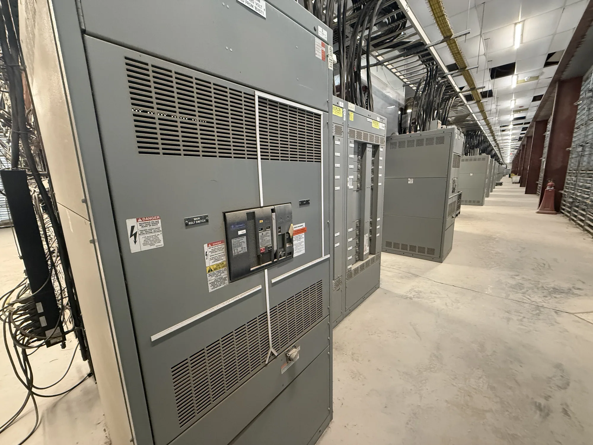
Apply arc-flash planning to the specified equipment
Metal-enclosed switchgear describes an equipment arrangement, not a single arc-flash performance level. Construction, switching devices, voltage class, compartment arrangement, grounding method, and intended access all depend on the project specification. A metal enclosure does not by itself eliminate arc-flash hazards or establish incident energy. The responsible engineer should evaluate the actual system and operating tasks, then coordinate study assumptions with the equipment design.
Arc-flash analysis commonly considers available fault current, protective-device characteristics and settings, system configuration, and the time required for a fault to clear. Incident energy and arc-flash boundaries are results of that analysis for defined conditions and working distances, not universal values that can be assigned to a product family. They may differ between locations or change when system conditions, settings, or equipment arrangements change.
Build a reliable study around real system data
Before finalizing equipment requirements, identify who will provide the short-circuit and coordination information, who will perform the arc-flash study, and which operating cases the analysis must cover. Relevant inputs may include the source configuration, transformer data, conductor lengths and sizes, protective-device types and settings, available operating modes, and the equipment connection points. The project engineer must determine which information is applicable and verify it against current drawings and field conditions.
Missing or assumed inputs can make a study less representative of the installation. If final settings, upstream protection, or system operating arrangements are not yet known, record that uncertainty and agree on how it will be resolved. The study should state its assumptions and identify the conditions it evaluates. Confirm whether commissioning or later system changes require updated analysis, labels, or operating documents; those responsibilities should be assigned in project planning.
Consider design choices without treating them as guarantees
Equipment design can affect how operators access and interact with components, but each option involves project-specific tradeoffs. Discuss switching-device type, compartment access, control arrangements, remote operation provisions, and maintenance access with the responsible engineer and manufacturer. A proposed feature should be described precisely in the specification, including its intended function and operating conditions. Do not assume a particular arrangement will reduce incident energy unless the qualified analysis evaluates it.
Protective-device selection and settings also involve coordination, continuity, and fault-clearing considerations. A setting chosen solely to reduce calculated energy could affect selectivity or other system objectives. Grounding and bonding details are part of the overall equipment and system design, but they do not replace an arc-flash study or safe work procedures. Confirm the grounding method, fault-clearing scheme, and relevant switching sequence with the project engineer for the specific installation.
Coordinate construction class, access, and work practices
Metal-enclosed equipment can differ by specified class and application, so clarify whether the project calls for low-voltage switchgear, medium-voltage switchgear, or another defined assembly. Do not transfer assumptions across voltage classes or equipment types. Specify the intended lineup arrangement, incoming and outgoing connections, metering and control needs, and access points. Ask which design details are available for the selected equipment and which must be confirmed through approved drawings.
Work practices remain essential regardless of enclosure design. The employer's electrical safety program and qualified personnel should determine hazard controls, boundaries, protective equipment, and procedures for each task under applicable requirements. The equipment specification should not imply that routine access is safe or that a design feature authorizes energized work. Installation, testing, operation, and maintenance belong to qualified personnel following applicable safety procedures.
Illustrative automotive manufacturing scenario
Consider an automotive manufacturing project planning a new metal-enclosed switchgear lineup to serve production loads. The source arrangement, fault-current values, device settings, operating modes, and equipment configuration are unknown at this planning stage; no incident-energy value or protective-equipment level can responsibly be inferred. The project team should provide verified system data and ask a qualified engineer to evaluate the relevant locations and operating cases.
Production continuity may make coordination between protective devices and operating procedures especially important, but no single setting or design option should be presumed suitable. The engineer can compare documented alternatives against safety and system objectives, explain assumptions, and identify information that remains unresolved. The manufacturer can review equipment requirements and configuration details against the project specification; the engineer remains responsible for study calculations and system conclusions.
Put study interfaces and documentation in the specification
Provide the manufacturer with the required voltage class, system arrangement, lineup dimensions or constraints, connection details, protective-device requirements, control and metering scope, and anticipated access needs. Include the latest one-line diagram and relevant study information when available, clearly noting preliminary data. Identify the responsible parties for study work, settings approval, drawing review, installation, commissioning, labeling, and future updates rather than leaving these interfaces implicit.
Ask the project team to confirm what documentation the equipment submittal should include, such as configuration drawings, device information, control schematics, and applicable ratings. Listing, testing, ratings, and standards applicability must be verified for the specific design and supplied assembly. For an eligible low-voltage switchboard, UL 891 applicability and assembly listing require specific confirmation; that standard should not be applied indiscriminately to switchgear or medium-voltage equipment.
Use a practical review checklist before release
Before releasing the specification, confirm the equipment class and application; verified system inputs and study ownership; protective-device coordination responsibilities; intended operating and service access; grounding and bonding requirements; and the documents needed for engineering review. Record open questions, assumptions, and approval points. Confirm availability and delivery timing for the actual configuration with the manufacturer, since both depend on the order and specification.
Arc-flash safety is best addressed as a coordinated project responsibility: qualified analysis defines hazards under stated conditions, equipment design supports the intended installation, and work practices govern tasks performed by qualified personnel. Use the review to resolve technical interfaces before approval, then keep study documentation aligned with the final equipment and system information. This approach supports an informed purchase of new switchgear without mistaking enclosure construction for a complete safety program.