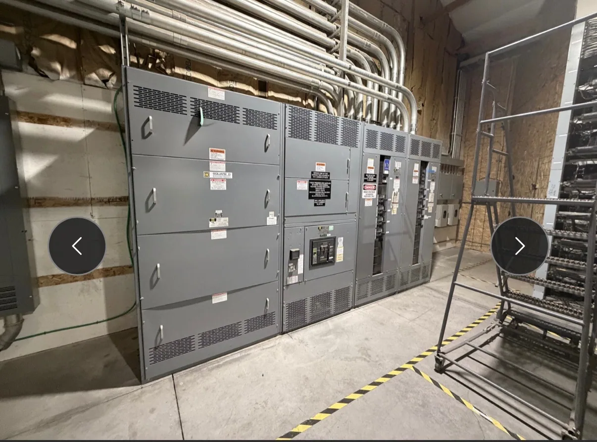
Start with the specified equipment and protection objective
Protective relay selection for metal-enclosed switchgear begins with the equipment’s defined class and intended role, not with a relay model in isolation. The construction, switching devices, available compartments, and permitted application depend on the equipment specification. Confirm whether the project calls for low-voltage switchgear, medium-voltage switchgear, or another defined assembly, and identify the circuits and sources the protection scheme must address.
Then establish what the scheme is expected to detect and what action it should initiate. A relay may monitor a feeder, transformer, tie, or incoming source, but the appropriate functions depend on the circuit, system study, and equipment. Identify required trip outputs, alarms, status indications, and any interlocking interfaces. The responsible engineer should document the protection objectives and approve the device functions and settings for the actual system.
Match sensing inputs to the system design
Relay inputs must correspond to the specified current and voltage sensing arrangement. Ask the project engineer to define which current transformers and voltage transformers, if any, supply each device; their locations, ratios, polarity, accuracy needs, and secondary wiring are design matters. The relay’s input capabilities must match those inputs. A relay selection cannot compensate for an unsuitable sensing arrangement or incomplete drawings.
Confirm which measurements and protection functions are required at each circuit. Depending on the application, the engineer may consider phase and ground current protection, voltage-based functions, frequency functions, or other device capabilities. These are not automatic requirements for every lineup. Grounding method, system configuration, available fault information, and the study affect the appropriate approach. Make those assumptions visible in the protection documents so reviewers can identify conflicts before equipment details are finalized.
Coordinate relay functions with switching and grounding
A protective function matters only in the context of the device it operates and the system response intended. Specify whether a relay is to trip a circuit breaker or interface with another defined control scheme, and identify required contacts, trip circuits, lockout functions, and alarms. Confirm that the selected switching device and control circuit support the intended operation. Do not assume every metal-enclosed assembly uses the same device arrangement or control logic.
Grounding and neutral details also affect protection decisions. Provide the system grounding configuration and describe any neutral sensing or ground-fault detection requirements for the responsible engineer to evaluate. Protection behavior must be coordinated with the actual source and circuit arrangement, including ties or alternate feeds when present. The engineer should resolve how the scheme behaves during relevant operating modes and document the assumptions, rather than relying on a generic function list.
Plan control power, access, and settings management
Identify the control-power source, nominal values, backup expectations, and the circuits that must remain available for protection and tripping. The required relay supply and control wiring depend on the selected device and design. Ask how loss of control power is to be indicated or handled, and confirm that the proposed arrangement fits the equipment documentation. These details can affect wiring, compartment planning, and coordination with the broader control system.
Specify the settings basis and who is responsible for providing and approving final values. Relay settings should come from the project’s protection and coordination work, not from an assumed example. Request the applicable device documentation, settings file or schedule where appropriate, and a clear record of revisions. Also coordinate physical access for inspection or adjustment with the equipment layout and project maintenance practices. Installation, testing, and maintenance should be performed by qualified personnel following applicable safety procedures.
Evaluate coordination tradeoffs with an engineer
Protection coordination balances sensitivity, selectivity, operating time, and the consequences of an interruption. A faster or more sensitive setting is not automatically preferable if it conflicts with upstream or downstream devices, system conditions, or the intended operating sequence. The qualified engineer must assess available fault information and system studies, then verify coordination across the operating configurations identified for the project. Confirm which party supplies studies, settings, and review comments.
For an illustrative automotive manufacturing project, a buyer might need to coordinate protection for a production feeder and a transformer supply while accounting for planned alternate feeds. No current, voltage, transformer data, or fault values are assumed here. The engineer would need actual one-line diagrams, equipment data, grounding information, and operating scenarios to evaluate functions and settings. Any applicable standards review and equipment-specific requirements must also be confirmed for the project.
Provide a complete relay and equipment specification
For a useful manufacturer review, provide the one-line diagram, equipment class and scope, system data, circuit descriptions, sensing-device information, grounding method, control-power requirements, and protection study or approved settings basis. Include relay function requirements, communications or monitoring interfaces if specified, trip and alarm logic, and the desired submittal documents. Identify which details are preliminary and who will resolve them. This helps distinguish mandatory requirements from options without inventing design values.
Also state the required enclosure and equipment characteristics separately from relay functions. Confirm the applicable construction, access, service conditions, and any requested assembly listing or testing against the specific design; availability and applicability require project-level verification. Do not treat a relay specification as confirmation of a complete equipment rating or compliance. The manufacturer can review the stated requirements and identify questions, while the project engineer retains responsibility for system protection decisions and final settings.
Coordinate submittals before releasing the design
Before procurement, align the relay schedule, one-line, control schematics, sensing details, and equipment specification. Resolve discrepancies in device tags, circuit names, trip destinations, and control-power assumptions through documented review. Ask for clarification where the intended function or interface is unclear, and confirm which revisions govern. This coordination reduces the risk that a technically correct relay is paired with the wrong sensing, wiring, or operating scheme.
South Carolina Switchgear Builders manufactures new switchgear and switchboards to specification, with US-built equipment, all-American components, and nationwide shipping. Availability and actual lead times depend on the order and must be confirmed. Share the project documents and open technical questions for review before finalizing the equipment scope; the responsible engineer should approve protection functions and settings, and project-specific configuration, delivery, and documentation should be confirmed against the final specification.