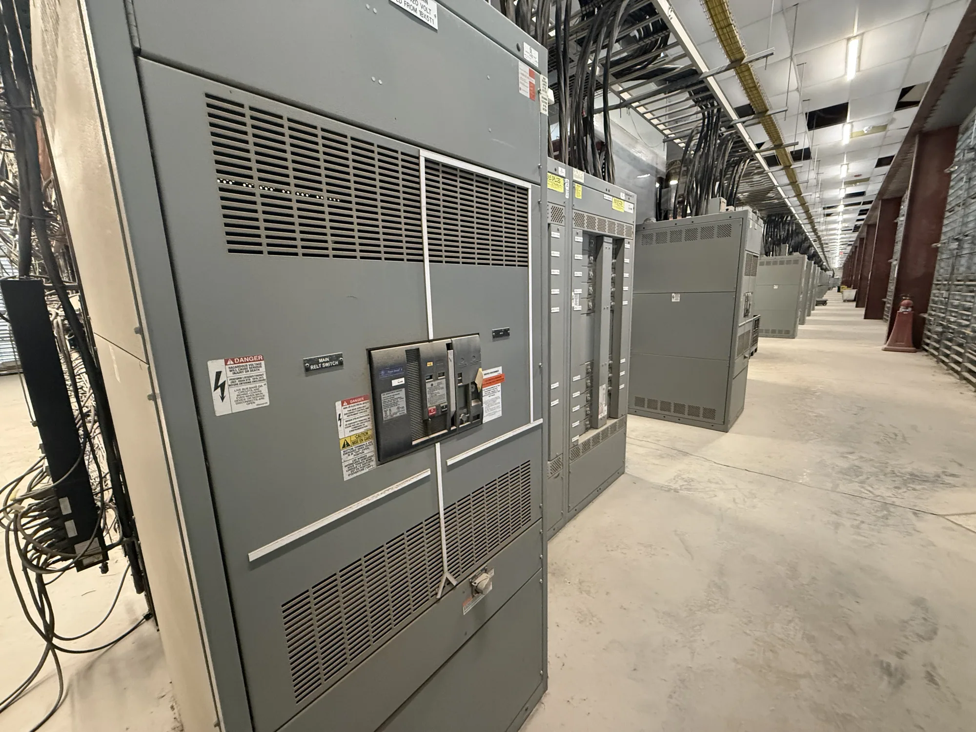
What continuous current means in a motor control center
A motor control center (MCC) groups motor branch circuits and control equipment in an assembly. Its continuous current rating describes a current-carrying capability stated for a specified part of the assembly and its defined conditions. It is not a substitute for reviewing the current ratings of individual bus sections, feeder devices, starters, drives, conductors, and other components.
For a project, distinguish the expected operating current of connected loads from the equipment ratings selected to serve them. A nameplate value, engineered load calculation, or measured operating profile may inform the design, but each has limits. Measurements reflect the conditions and operating state at the time they were taken; a projected installation may require additional analysis and confirmation by the responsible engineer.
Read the rating in the context of the assembly
Ask exactly what the specified current rating applies to: the horizontal bus, a vertical bus section, a feeder circuit, a unit, or another defined component. The assembly rating does not establish that every device or circuit can carry the same current. Review the complete equipment schedule and manufacturer documentation so the lowest applicable component limit and its conditions are understood.
Motor circuits also involve starting, acceleration, and operating patterns that differ from a simple constant load. Starter selection, drive configuration, feeder protection, conductor sizing, and coordination must be addressed for the actual application. A continuous current rating alone does not establish motor-starting capability, short-circuit performance, protective-device suitability, or compliance with the project’s electrical design.
Load assessment and future capacity
Develop a load schedule that identifies each motor, its intended operating role, and the design information available for its circuit. Include applicable nameplate data and the engineer’s assumptions for simultaneous operation, duty, starting method, and any drive-fed loads. Where measured data are used, document when and how measurements were obtained and whether they represent normal, peak, or unusual operating conditions.
Future capacity should be a deliberate design choice, not an undefined allowance. Identify anticipated motors, planned process changes, and any desired spare units, then ask the engineer to evaluate their effect on bus, devices, space, and protection. Adding nominal capacity does not automatically make an MCC suitable for every future load; available configurations and rating conditions must be confirmed for the actual design.
Operating temperature and derating conditions
Current capability can depend on the equipment’s specified configuration and operating environment. Provide the expected ambient temperature, enclosure and installation details, ventilation constraints, and any other conditions that may affect heat dissipation. Confirm the applicable manufacturer instructions and design assumptions rather than treating a published rating as unconditional. If derating or another adjustment is needed, its basis should be documented for the specific assembly.
Heat is also influenced by the combination and operation of devices within an MCC. Starters, drives, protective devices, loading patterns, and enclosure arrangements may affect thermal conditions. The project team should identify relevant operating scenarios and ask how the proposed arrangement addresses them. Do not infer a rating from a similar-looking lineup or assume that a general temperature statement applies to every unit and bus section.
Illustrative application: automotive manufacturing
Consider an automotive manufacturing area adding motor circuits for a process line. The motor quantities, loads, duty cycles, ambient conditions, and future expansion needs are unknown in this example; no rating can be selected from the industry label alone. The project engineer would need the actual motor schedule and operating assumptions, including which loads run together and whether drives or particular starting methods are planned.
That information can guide review of feeder and unit ratings, bus loading, thermal conditions, and protective-device coordination. The engineer should also determine which applicable standards and project requirements govern the assembly and verify the proposed equipment documentation. This scenario is illustrative, not a design recommendation: the correct continuous current rating depends on verified project inputs and the specific MCC configuration.
Information to include in an MCC specification
- Provide system voltage and project electrical documents, along with the motor schedule, available nameplate data, and engineered load assumptions.
- Identify expected simultaneous operation, starting methods, drive-fed motors, anticipated duty, and any planned future loads or spare-unit requirements.
- State the required rating for each relevant bus section, feeder, and device, and request confirmation of the conditions and configuration to which each rating applies.
- Document ambient and installation conditions, including enclosure, ventilation, and any project-specific thermal considerations.
- Identify required protective-device coordination, short-circuit information, drawings, submittals, standards review, and acceptance documentation for the project.
- Ask which items are included or excluded, what assumptions need approval, and what equipment-specific ratings, testing, listing, or delivery details must be confirmed.
For a new MCC quotation, provide the one-line diagram, motor schedule, load basis, environmental conditions, and project requirements as early as practical. South Carolina Switchgear Builders manufactures new motor control centers to specification, with US-built equipment and nationwide shipping; configuration, applicable ratings, documentation, availability, and delivery timing depend on the order and must be confirmed. Have qualified project personnel review the proposed equipment and installation requirements before procurement and use.