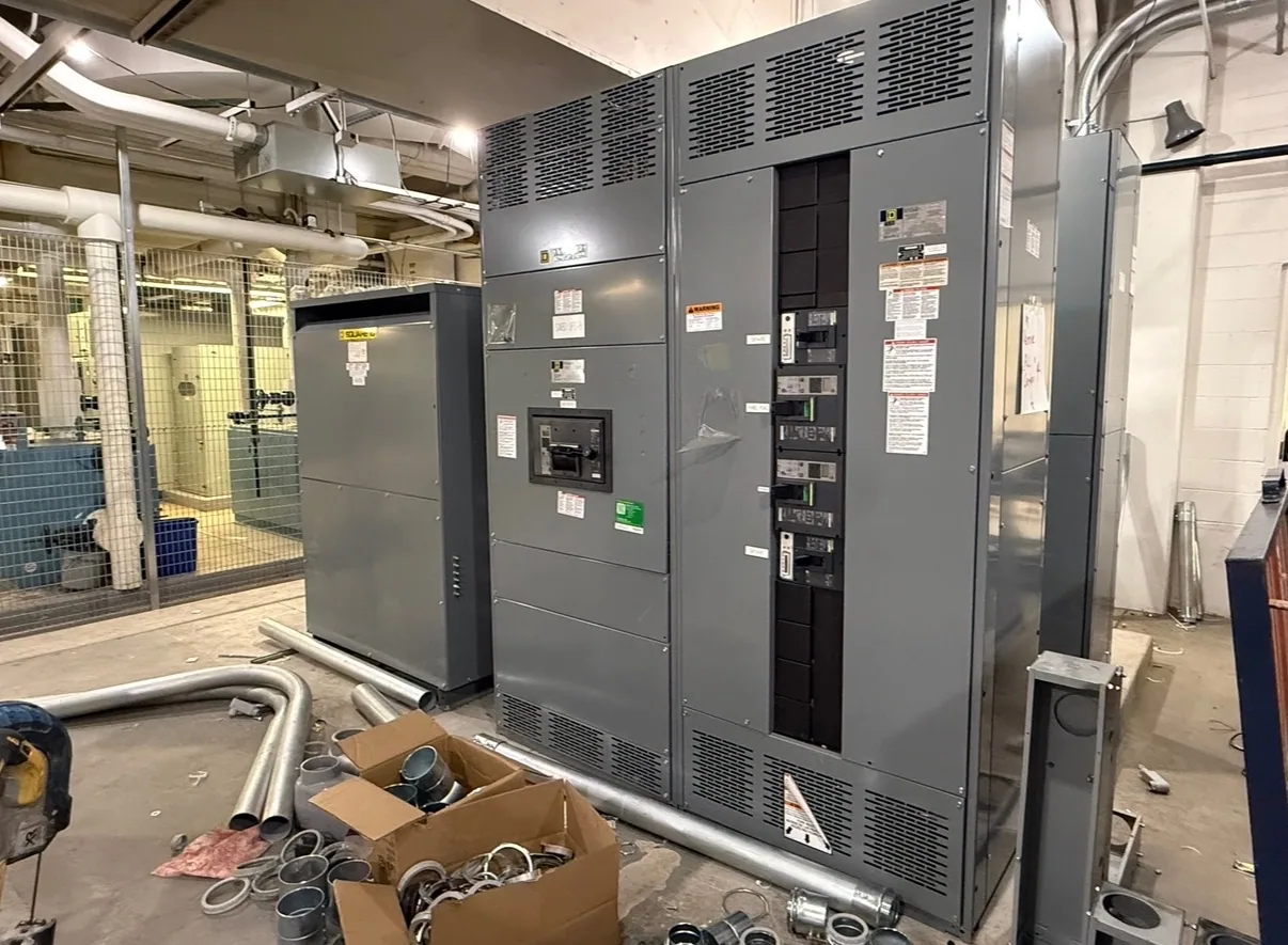
What selective coordination means for an MCC
In a motor control center (MCC), selective coordination concerns the time-current behavior of upstream and downstream protective devices. For a fault on a motor branch circuit, the intended result is for the device nearest that fault to operate before an upstream device, within the specified range of fault current and operating conditions. The objective is to limit unnecessary loss of power to other circuits, not to guarantee that every fault affects only one load.
This is an equipment-specific design question, not another name for switchgear. An MCC groups motor branch circuits and associated control equipment in a coordinated assembly. Its feeder protective device interacts with branch-circuit fuses or circuit breakers, motor starters, and, where specified, drives and other controls. The actual device combinations and performance must be reviewed against the project requirements and the supplied configuration.
Define the required coordination range
“Selective coordination” is incomplete as a specification unless the required range and applicable project criteria are stated. Ask the responsible electrical engineer to identify the fault-current range over which coordination is required, which upstream devices are in scope, and whether the requirement applies to particular loads, distribution paths, or the entire installation. Governing codes and project documents may impose requirements, but applicability must be determined for the project rather than assumed.
Coordination depends on more than comparing nominal device ratings. Time-current curves provide one important view of device response, while available fault current, current-limiting behavior, tolerances, and manufacturer data may also affect the evaluation. Curves that appear separated do not by themselves establish performance across every condition. Have the engineer confirm the appropriate method and supporting data for the specified devices, including the system conditions used in the study.
Balance continuity with protection
Increasing separation between upstream and downstream operating characteristics can help reduce the chance that a branch-circuit fault trips a feeder device. But changing trip settings or selecting a different protective device also affects clearing time and protection objectives. The design must balance continuity of service with the required protection of conductors, equipment, and people. Coordination cannot be evaluated in isolation from the project’s fault-current, protection, and safety requirements.
Motor loads add practical constraints. Starter type, motor characteristics, overload protection, and branch-circuit device selection must fit together. A variable-frequency drive may introduce manufacturer-specific input protection and installation requirements, which should be checked for the selected drive and circuit. Feeder devices, enclosure arrangement, and expected loading can also influence thermal design. Do not assume that a device combination proven for one MCC applies to another lineup or operating condition.
Consider operating changes and future loads
Future motor additions can alter feeder loading and protection assumptions, even when spare spaces are available. Identify planned expansion, anticipated motor sizes or drive use, and any required reserve capacity early. A spare compartment is not proof that a future circuit can be added without revisiting available fault current, coordination, heat, or assembly configuration. The engineer should define which assumptions are fixed and which need review when the system changes.
For example, an automotive manufacturing project might have separate motor loads serving production equipment and building systems. If a branch fault occurs, the project team may want unaffected functions to remain supplied. This is only an illustrative scenario: actual voltage, fault current, device selections, operating priorities, and coordination requirements are unknown until established from project documents. The qualified engineer must calculate and review the real system; no particular outcome should be presumed.
Provide the information needed for review
When requesting a new MCC, share the one-line diagram, system voltage and frequency, source and transformer information, available fault-current data, and the required protective-device coordination range. Include feeder and branch-circuit requirements, motor and drive schedules, starter types, control-power needs, and any known future loads. Identify applicable project specifications and code requirements, while asking the engineer to confirm which provisions govern the installation.
Also state the intended environment and installation constraints, including enclosure requirements, cable entry preferences, space limitations, and interfaces with upstream and downstream equipment. Clarify whether the supplier is expected to provide specific device data, curves, or submittal documents, and who will perform the system study. These details help distinguish equipment design information from calculations and approvals that belong to the project’s responsible engineering team.
Specify evidence, boundaries, and coordination
Request documentation that matches the actual proposed assembly and device combination. Confirm what information can be provided for review, what assumptions it depends on, and whether any coordination conclusions come from a project-specific study or manufacturer data. Ask how changes to protective devices, settings, motors, or source conditions affect those conclusions. Listing, ratings, testing, and standards applicability must be verified for the specific equipment and specification.
Before release, align the MCC supplier, electrical engineer, system-study provider, installer, and owner on responsibilities and review milestones. Confirm feeder and branch-device scope, drawing and submittal expectations, interface details, and the process for resolving deviations. Installation, testing, and maintenance should be performed by qualified personnel under applicable safety procedures. A clear, equipment-specific specification lets the team evaluate continuity goals without treating coordination as a universal promise or substitute for engineering review.