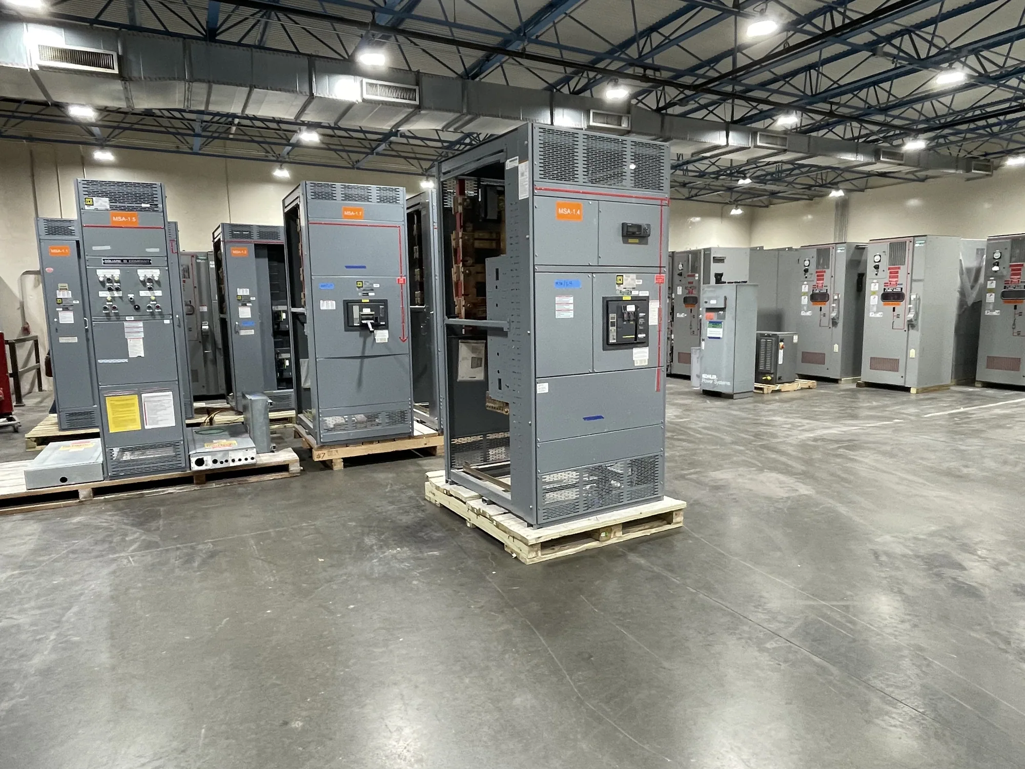
Where grounding and bonding enter the equipment design
Grounding and bonding for outdoor switchgear are not details to resolve by selecting a generic accessory. They connect the distribution system, the equipment assembly, its enclosure, and the site installation. The design must distinguish the equipment grounding path from the grounded circuit conductor and establish how conductive parts are bonded. The applicable arrangement depends on the system and project design, so the responsible engineer should define it.
For equipment supplied by South Carolina Switchgear Builders, provide the intended application and electrical one-line information early. Identify whether the project calls for low-voltage switchboards or medium-voltage switchgear, and state the system voltage class and service arrangement. The equipment design must follow the confirmed specification; grounding details cannot be inferred from an outdoor enclosure or a product label alone. New equipment is custom to specification, with configuration and availability confirmed for each order.
Clarify neutral treatment and service arrangement
Neutral treatment depends on the system configuration and where the relevant bonding point belongs. Tell the project team whether a neutral is present, how the source and downstream distribution are arranged, and whether the assembly is intended to serve as service equipment or as downstream equipment. These descriptions are project inputs, not assumptions for the manufacturer to resolve without engineering direction. The responsible electrical engineer should review the one-line diagram and applicable code requirements.
Ask the engineer to identify which conductors and exposed conductive parts require bonding within the assembly and what connection provisions the equipment must include. Also clarify interfaces with the site grounding system and any separately specified grounding components. Avoid treating a neutral-to-enclosure connection as interchangeable with equipment bonding. The proper relationship depends on the particular system; the final drawings and supplied equipment must reflect the approved project design.
Coordinate outdoor enclosure and site interfaces
Outdoor installation adds physical interfaces that can affect grounding details. Enclosure construction, entry locations, mounting arrangement, foundation design, and access for installation and maintenance should be coordinated with the site layout. Provide the expected cable or conduit entry directions and identify where site conductors approach the equipment. The project team can then review how the specified connections are to be reached and protected without assuming unprovided enclosure features.
Moisture exposure and the surrounding environment are also relevant to the equipment specification. Describe the installation location and environmental conditions, including any known exposure that could influence enclosure selection or material requirements. Coordinate foundation and enclosure details with the civil and electrical plans, and identify clearances needed for qualified personnel to perform installation and maintenance under applicable safety procedures. Do not rely on the enclosure alone to establish a suitable grounding path or resolve site conditions.
Review the engineering trade-offs
Consider a hypothetical food and beverage facility planning outdoor distribution equipment near a process area. The available information may not yet establish the service arrangement, grounding-electrode details, environmental exposure, or future expansion needs. Those are unknown project values, not assumed design conditions. The engineer should review the one-line, fault-current and protection information, applicable code, and site requirements before specifying grounding and bonding provisions.
Trade-offs can include where to locate equipment, how to route conductors, and how to retain maintenance access while coordinating the foundation and cable entries. A compact layout may reduce available working space; a preferred entry path may conflict with site routing. These choices require project-specific review rather than a universal recommendation. The food and beverage example illustrates coordination needs only; no particular process condition, rating, or standard is implied.
Information to include in a specification request
For a useful equipment review, provide the current one-line diagram, system voltage class, phase and wire arrangement, source information, and intended service or downstream role. Include available fault-current and protective-device information when established by the engineer, along with the required equipment ratings and any specified standards. Mark values that are pending rather than filling gaps with estimates. State the required neutral arrangement and describe the project’s grounding and bonding design intent.
Also provide the outdoor location, environmental and exposure conditions, foundation or mounting concept, cable-entry plan, access constraints, and relevant site grounding interfaces. Identify drawing and submittal expectations, project schedule requirements, and the parties responsible for engineering approval and field installation. These inputs help determine whether the proposed equipment configuration matches the project. Availability and actual lead times depend on the order and must be confirmed; delivery dates and design-specific features require confirmation as well.
Submittals, boundaries, and project coordination
Use equipment submittals to verify that the proposed assembly and its drawings correspond to the approved specification. Review grounding and bonding provisions, neutral treatment, connection locations, enclosure and entry details, and interfaces with site work. Confirm any listing, testing, ratings, or standards only against the actual design and supplied equipment. UL 891 may apply to eligible low-voltage switchboards, but applicability and assembly listing must be verified for the specific design; it does not establish requirements for medium-voltage switchgear.
Clearly separate equipment scope from site scope. The specification should state which grounding conductors, electrodes, terminations, and installation work are furnished with the assembly and which are by others, rather than leaving responsibility implicit. Resolve discrepancies between drawings, schedules, and notes before release for manufacture. Qualified personnel must handle installation, testing, and maintenance using applicable safety procedures. With the system design, site interfaces, and scope documented, the manufacturer can review the new equipment request against the project specification and identify open questions for resolution.