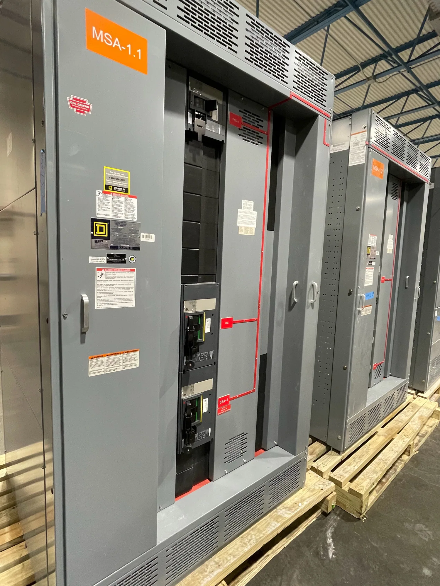
What continuous-current ratings mean at the service entrance
For service-entrance switchgear, continuous-current ratings help describe the current the assembly and its components are specified to carry during normal operation. They are not a substitute for determining the facility’s expected demand or checking the complete equipment design. The project engineer must coordinate the anticipated load with the ratings of the bus, service disconnect, and other current-carrying devices identified in the proposed lineup.
A service entrance also brings utility-interface and installation requirements into the equipment decision. The drawings and specification should clearly identify the point of service, incoming arrangement, service disconnecting means, and any required metering or protection provisions. Which provisions apply depends on the project and the serving utility’s requirements; they should be confirmed for the actual installation rather than inferred from a general product description.
Coordinate load assumptions with bus and device ratings
Begin with a documented load basis. This may include measured demand for an existing facility, an engineered load calculation for a new installation, planned process additions, and the assumptions used for diversity or future capacity. The responsible engineer should establish the design current and explain how operating schedules, large motors, variable loads, and anticipated expansion affect the selected equipment. A single nameplate total may not represent the expected service demand.
Then review the proposed current rating as a system of related component ratings. Bus and protective or switching devices may have their own specified ratings and application limits. Confirm that the equipment schedule and single-line diagram identify the intended ratings and that the proposed assembly is suitable for the documented load and installation conditions. Do not assume that a higher rating on one component automatically determines the rating or capability of the complete lineup.
Account for operating conditions and temperature
Ratings must be evaluated against the conditions under which the equipment will operate. Relevant project information can include ambient temperature, indoor or outdoor placement, enclosure arrangement, ventilation, nearby heat sources, altitude where applicable, and expected loading patterns. The effect of any condition on the allowable application or required design must be verified against the specific equipment configuration and its documentation. Avoid applying a generic derating factor without engineering support.
Operating temperature is connected to loading, installation, and equipment design; it is not an independent promise that the switchgear will run at a particular temperature. Specify environmental conditions and ask the manufacturer to identify applicable assumptions, limitations, and documentation for the proposed assembly. If site conditions differ from those used in the equipment design, resolve that difference before approval. Qualified personnel should perform installation, testing, and maintenance under applicable safety procedures.
Coordinate the utility interface and service details
Continuous-current selection does not settle every service-entrance requirement. The project team must coordinate incoming conductors and termination provisions, service disconnect location, grounding and bonding approach, metering interfaces, and any utility-required details with the one-line diagram and project specifications. Responsibility for each interface should be clear among the engineer, utility, installer, and equipment supplier. Utility-specific requirements should be obtained from the serving utility for the actual project.
Review the complete service design with short-circuit and protective-device requirements as separate but coordinated topics. Continuous-current ratings address normal current-carrying application; they do not by themselves establish short-circuit withstand capability, interrupting suitability, or protection settings. The engineer should specify and verify each requirement independently, then confirm that the selected equipment arrangement supports the coordinated design.
Illustrative example: an automotive manufacturing facility
Consider an automotive manufacturing project adding a new production line to an existing service. Its future demand, motor duty, operating schedule, and available service capacity are unknown until the project team supplies verified data. No current rating can responsibly be selected from the industry name alone. The engineer would establish the load basis, evaluate the new and existing loads together, and document the conditions that govern the proposed service equipment.
The team would also confirm utility-interface details, the required service disconnect arrangement, environmental conditions, and any planned expansion. Those facts may affect equipment configuration and rating selection, but their effects must be evaluated for the actual design. The manufacturer can review the requested specifications and identify questions or equipment-specific limitations; the responsible engineer retains the role of validating calculations, code application, and project approvals.
Information to include in a specification inquiry
- Provide the single-line diagram, service voltage and phase information, incoming arrangement, and the intended service-entrance function.
- State the calculated or measured load basis, expected operating profile, planned additions, and the requested continuous-current ratings for the assembly, bus, and devices.
- Describe the installation environment, enclosure and location requirements, ambient conditions, and any project-specific operating constraints.
- Identify utility criteria, metering needs, grounding and bonding requirements, protection coordination inputs, and required drawings or submittals.
- List applicable project standards and approval expectations, asking the responsible engineer to confirm their application to the specific design.
Review the proposed equipment before release
Before approving submittals, compare the equipment schedule with the one-line diagram, load calculations, utility criteria, and installation conditions. Resolve discrepancies in ratings, device arrangement, terminations, or environmental assumptions in writing. Ask which documents confirm the offered assembly configuration and what exclusions or project inputs remain open. Listing, testing, ratings, availability, and delivery timing must be confirmed for the specific equipment and order.
South Carolina Switchgear Builders manufactures new switchgear to specification, with US-built equipment and all-American components, and ships nationwide. Availability and actual lead times depend on the order and require confirmation. A clear, coordinated specification gives the project team a sound basis to evaluate continuous-current suitability and move toward an equipment proposal without treating one rating as a substitute for complete engineering review.