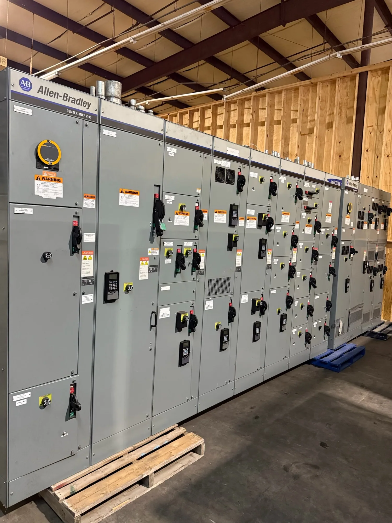
Define the service-entrance equipment scope — Service-Entrance Switchgear: Grounding and Bonding
Service-entrance switchgear is part of the interface between a utility supply and a facility’s main electrical distribution. Grounding and bonding provisions cannot be specified in isolation: their application depends on the electrical system, the service disconnect arrangement, neutral configuration, and the project’s adopted requirements. Start by establishing what equipment is included and where the service boundary lies.
Clarify whether the procurement covers the incoming service section, service disconnecting means, distribution sections, metering provisions, or some combination. Identify which components and connections are within the switchgear supplier’s scope and which are furnished or completed by others. The one-line diagram, equipment arrangement, and responsibility matrix should describe the same boundary so grounding conductors, bonding connections, and neutral treatment are not left to assumption.
Coordinate neutral treatment with the system
The neutral’s role depends on the source and service configuration. The design team should state whether a grounded conductor is present, how it is arranged at the service, and where the system’s intended neutral-to-ground relationship is established. Avoid relying on a generic note such as “ground per code” to communicate the required equipment configuration; it does not tell a manufacturer which neutral and bonding details the approved design calls for.
For the equipment specification, identify the neutral bus requirements, relevant connections, and any intended separation between neutral and equipment grounding paths within the assembly. The responsible engineer must resolve these details against the complete service design and applicable code. The utility’s interface requirements and authority having jurisdiction review may also affect the final arrangement. Confirm these inputs before drawings are approved, rather than treating them as field decisions after fabrication.
Address bonding and equipment grounding paths
Bonding connects conductive parts as required by the design, while the equipment grounding path supports the intended fault-current return path. Specify which enclosure sections, doors, barriers, and other conductive parts require bonding provisions, and describe how the equipment grounding conductor or grounding bus connects through the assembly. The actual arrangement must suit the specified equipment and be verified by the project engineer.
Also identify the incoming grounding connection, bus location, and any connection points needed for outgoing feeders or adjacent equipment. State conductor material and termination expectations when the design requires them; do not assume all project conductors, lugs, or external grounding components are part of the switchgear supply. The switchgear submittal should show relevant buses and connection locations clearly enough for the engineer to check continuity and coordination with the installation drawings.
Resolve utility and approval interfaces early
Utility service requirements can influence metering compartments, service disconnect details, access, and the location of incoming connections. They do not replace the facility engineer’s responsibility to define the grounding and bonding design. Provide current utility documents and identify any utility review milestones that affect equipment layout or approval. If requirements are not yet confirmed, list them as open items rather than allowing an unverified assumption into the purchase specification.
Applicable code requirements and the authority having jurisdiction also need project-specific review. The responsible electrical engineer should determine which adopted provisions govern the installation and how they apply to the selected service arrangement. Equipment drawings can document the manufacturer’s supplied configuration, but they do not establish that every installation condition, field connection, or site grounding electrode arrangement is correct.
Illustrative facility scenario and trade-offs
Consider a food and beverage facility planning new main distribution equipment at a utility service entrance. Its process loads, building services, and possible separately derived systems may call for careful coordination, but no voltage, fault-current value, source arrangement, or neutral scheme can be presumed from the facility type alone. The engineer must establish those values and arrangements from the project design and confirmed utility information.
A compact lineup may simplify a constrained equipment room, while access for terminations and clear identification of grounding connections can require different layout choices. These are design trade-offs, not reasons to omit required bonding or alter neutral treatment. Ask the engineer to resolve calculations, applicable standards, and approval requirements, then provide the resulting requirements to the switchgear manufacturer for design review.
Prepare a complete specification and submittal review
Before requesting a quotation, provide the one-line diagram, service characteristics, equipment ratings, utility interface information, layout constraints, and the required neutral and grounding configuration. Include conductor and termination requirements, metering or compartment needs, project standards, and the identity of parties responsible for field connections. Mark unknown values and pending approvals explicitly. This gives the manufacturer a sound basis to identify scope questions and develop equipment to the confirmed specification.
- Define service and equipment boundaries, incoming source details, and service disconnect arrangement.
- State the neutral configuration, grounding bus requirements, bonding provisions, and connection locations.
- Provide applicable project documents, utility requirements, equipment layout, and approval status.
- Identify included accessories and components, plus exclusions and work by others.
- Review submittal drawings for alignment with the approved one-line and installation responsibilities.
Confirm whether drawings will show the relevant grounding and bonding features and which project details remain subject to engineering or utility approval. Any listing, ratings, testing, and configuration must be verified against the actual supplied assembly; applicability is design-specific. Availability and delivery timing likewise depend on the order and must be confirmed. Installation, inspection, testing, and maintenance are work for qualified personnel following applicable safety procedures.
Carry approved details through procurement
When comments are resolved, maintain a consistent record of the approved one-line, equipment drawings, specification, and responsibility assignments. Changes to the service arrangement or neutral treatment should go through the project’s engineering and approval process before they are incorporated into the equipment design. This discipline helps the switchgear supplier, utility, installer, and facility team work from the same defined configuration.
For new service-entrance switchgear, the useful outcome is not a generic grounding note but a documented arrangement that fits the project’s system and supply scope. Submit the design inputs early, flag unresolved interfaces, and have qualified project professionals confirm calculations and code application. Then review the equipment-specific drawings against those decisions before authorizing production.