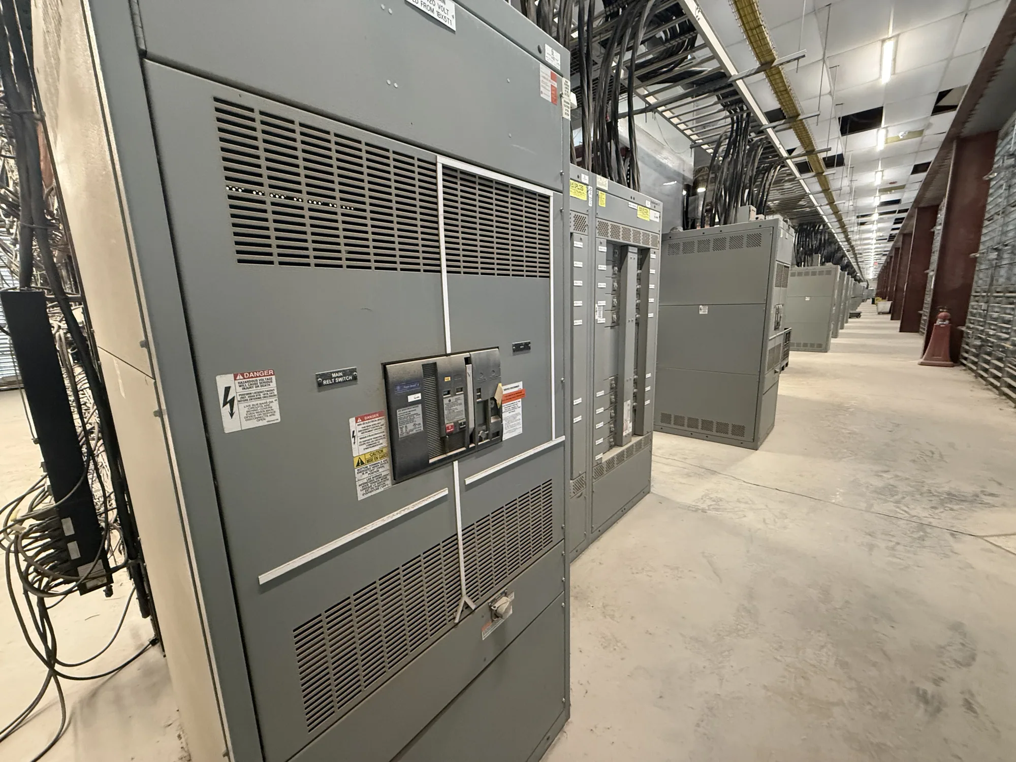
Define the role of information at the service entrance
Service-entrance switchgear sits at a consequential boundary in a facility’s electrical distribution system. Instrumentation and communications can help operators understand incoming power conditions and equipment status, but only when the specification identifies what information is needed, who will use it, and how it will reach the intended monitoring system. These choices belong alongside the electrical design, not as a late controls add-on.
Start by distinguishing local indication from remote monitoring. A meter or display may serve personnel at the equipment, while selected measurements or status points may be communicated to a building management system, supervisory system, or other owner-designated platform. The intended use affects the point list, interface, and documentation. It does not establish that any particular measurement, protocol, or network connection is included in a proposed assembly.
Build a point list around decisions
List the measurements and states that operators actually need. Depending on the design and approved equipment, a project may consider electrical measurements, breaker position, trip indication, or alarms. Treat these as candidate requirements rather than assumed features. For each point, state its purpose, required indication, source device, destination, and whether it is needed locally, remotely, or both.
Separate essential operational information from desirable detail. A concise, reviewed point list is easier to coordinate than a broad request to “provide monitoring.” Define naming conventions, units, scaling, alarm behavior, and any required time or event context where relevant. The responsible engineer and controls integrator should confirm which data can be supplied by the selected devices and how it will be interpreted by the receiving system.
Coordinate interfaces and responsibilities
Identify who supplies and configures meters, communication-capable devices, gateways, network switches, cabling, and software. The switchgear manufacturer, electrical contractor, controls integrator, owner’s IT group, and utility may have different scopes. Put those boundaries in writing, including who provides field wiring, network addressing, configuration files, point-to-point checks, and final system integration. Do not assume a physical port means the complete monitoring system is furnished.
Specify the accepted protocol and interface only after the receiving system’s requirements are known. Confirm whether communication is expected through a direct device connection, a gateway, or discrete hardwired points. Clarify the required medium, connector, message or register documentation, and any interface limitations. The project team should resolve interoperability and responsibility for protocol mapping before equipment approval, rather than relying on a generic statement that the assembly is “network ready.”
Keep cybersecurity boundaries explicit
Remote visibility can introduce questions beyond electrical design. State whether the equipment interface is intended to connect to an owner network, an isolated controls network, or no network at all. Define who approves access, assigns addressing, manages credentials, and controls remote connections. Avoid assuming the switchgear supplier will establish the owner’s cybersecurity policy or authorize connection to a production network.
Ask the responsible IT and controls teams what device documentation and configuration information they require. Establish whether communications are read-only, whether remote commands are permitted, and how access will be restricted and maintained. Any remote control function needs explicit engineering review and clear operating responsibility. Keep the boundary between monitoring and control unambiguous in the specification and submittal review.
Account for service-entrance design dependencies
Instrumentation does not replace decisions about the utility interface, service disconnect, grounding and bonding, protection, or equipment arrangement. Those elements depend on the project design and applicable utility and authority requirements. The qualified project engineer should coordinate the proposed measurements and status points with the one-line diagram, device selection, metering requirements, and approval process. Confirm any utility-specific interface directly through the project team; requirements are not universal.
For an automotive manufacturing facility, for example, a project team might consider whether incoming measurements and selected breaker status should be visible to plant operations. The required values, devices, protocol, network destination, and operating needs are unknown until the owner and engineer define them. The engineer must perform applicable calculations and review standards, protection, and utility requirements; the example is not a prescribed design or a statement of an available configuration.
Prepare a useful equipment specification
Provide the manufacturer with the project one-line diagram, service characteristics, intended equipment arrangement, applicable utility criteria, and the required point list. Identify the receiving system, accepted protocol or hardwired interface, and the parties responsible for field connections and integration. Include environmental and installation constraints that affect the proposed assembly, along with requested documentation and submittal milestones.
- Mark each point as required, optional, local, or remote, and identify its intended user.
- State interface expectations and identify who supplies devices, wiring, gateways, network configuration, and software.
- List required drawings, device data, communication documentation, and review or approval steps.
- Ask which features, ratings, listing, testing, and delivery details apply to the specific proposed equipment; confirm them against the project specification.
Review the resulting submittal with electrical, controls, operations, utility-coordination, and IT stakeholders before release. Resolve omissions and interface questions while changes can still be coordinated with the equipment design. For a new custom-to-specification assembly, availability and actual lead times depend on the order and must be confirmed. A complete point list and clear scope boundaries give the manufacturer and project team a practical basis for confirming the proposed configuration and planning integration.