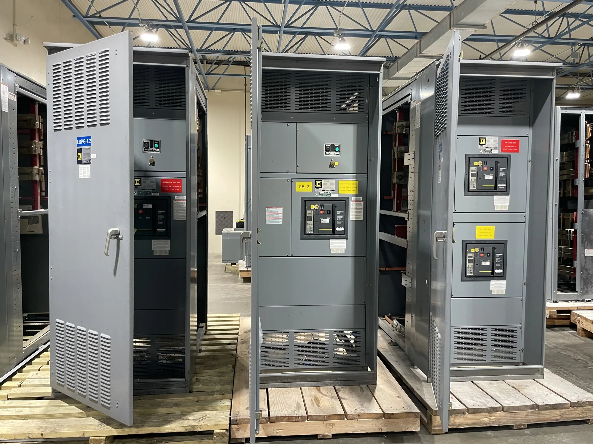
Where coordination enters the service-entrance design
Service-entrance switchgear is part of the main distribution system between a utility source and a facility’s downstream circuits. Selective coordination concerns how protective devices respond relative to one another when a fault occurs. The design objective is to have the device nearest the fault operate first, where the specified conditions permit, while upstream protection remains available for faults its downstream devices do not clear.
That behavior is not determined by the switchgear enclosure or a single breaker setting alone. It depends on the selected protective devices, their time-current characteristics, the source and distribution system, and the range of fault conditions the project requires the design to address. A coordination study and the governing project requirements should establish the applicable scope; the equipment specification should translate that scope into clear, reviewable requirements.
Define the operating range before selecting devices
Ask the responsible engineer to identify which portions of the distribution system must coordinate and under what conditions. The required range may be shaped by the project’s applicable codes, owner criteria, system configuration, and the specific downstream loads or circuits. Avoid assuming that a general statement such as “fully selective” defines the required boundaries or proves coordination at every possible fault current.
Time-current curves help compare device behavior, but a curve review must use the actual proposed devices and relevant settings. Consider both the lower-current region, where trip delays can influence continuity, and higher available fault currents, where protective devices may operate quickly or enter regions that require additional evaluation. The engineer should identify any overlap, limitations, or exceptions and document the basis for accepting them.
Balance continuity with protective performance
Longer intentional delays in upstream protection can help downstream devices clear certain faults first, but delays cannot be chosen in isolation. They must be assessed against equipment withstand, available fault current, protection objectives, and the project’s applicable requirements. A coordination goal does not justify settings that compromise the protection of conductors or equipment. The engineer must evaluate the complete system and document how the proposed arrangement addresses competing objectives.
Device selection also affects operational flexibility and future changes. Adjustable settings, trip-unit options, and the relationship between main and feeder devices may influence how the design can be commissioned or revised. Confirm which settings are fixed, adjustable, or field-configured, who is responsible for final settings, and what approved documentation will accompany the supplied equipment. Do not treat preliminary settings as final without engineering review.
Coordinate utility interface, disconnect, and grounding
At a utility service entrance, the service point and available source information influence the system model. Obtain the utility’s applicable service details through the project team, including available fault-current information and any stated interface requirements. The equipment design should be developed against the confirmed project data rather than assumed values. Utility requirements, approvals, and the authority having jurisdiction should be addressed by the responsible parties for the specific installation.
Service disconnect configuration and grounding and bonding arrangements are also part of the design context. Their details depend on the specified system and applicable requirements, so the project engineer should define the intended arrangement and confirm its treatment in the equipment documents. Review enclosure requirements, incoming conductor provisions, barriers, and access needs alongside electrical coordination; a coordination objective alone does not establish that the complete service-entrance assembly suits the site.
Illustrative manufacturing scenario and tradeoffs
Consider an automotive manufacturing facility with a service entrance feeding process equipment, building systems, and production-area distribution. This is an illustrative scenario, not a description of a particular installation; source characteristics, loads, device types, and fault-current values are unknown. If a fault affects one downstream circuit, the design team may seek to limit the outage to that circuit while maintaining appropriate upstream protection.
The engineer would need actual system data and device characteristics to assess whether that objective is achievable across the specified range. Production continuity may favor selective operation, while protection and equipment constraints may limit delay choices. The study should identify where coordination is demonstrated, where it is not, and what operational consequence follows. Qualified engineering review—not a generic rule of thumb—should resolve the tradeoff and support the final settings and approval package.
Information to provide with an equipment specification
- Identify the service configuration, nominal system details, source information, and confirmed available fault-current data, including the source and date of the data.
- Provide one-line diagrams, downstream device schedules, conductor and load information, and the defined coordination boundaries or required operating range.
- State applicable project requirements, desired device operation, required study deliverables, and who approves calculations, device selections, and final settings.
- Specify service disconnect and grounding and bonding requirements, enclosure conditions, incoming and outgoing provisions, and any project-specific documentation or approval needs.
Also identify equipment interfaces or exclusions that affect the study. For example, clarify whether downstream devices are part of the same procurement, supplied separately, or represented by project-provided data. Ask the design team to flag assumptions that depend on equipment not yet selected. This prevents a switchgear submittal from appearing to confirm coordination that can only be evaluated after the broader system and its actual protective devices are defined.
Review submittals and coordinate the next step
Before release, compare the equipment submittal with the approved one-line diagram, device schedule, and coordination-study assumptions. Confirm that device catalog selections and proposed settings match the reviewed design, and resolve discrepancies through the responsible engineer. Ask which documents will be provided for review and what information remains subject to confirmation. Final assembly details, ratings, availability, and delivery timing depend on the actual specification and order.
South Carolina Switchgear Builders manufactures new equipment to specification, with US-built equipment, all-American components, and nationwide shipping; configuration and availability must be confirmed for the project. Provide the engineering requirements and interface data early so the equipment proposal can be evaluated against the intended application. Installation, testing, and maintenance should be handled by qualified personnel under applicable project safety procedures. A clear coordination scope makes the design review and equipment procurement more useful to the entire project team.