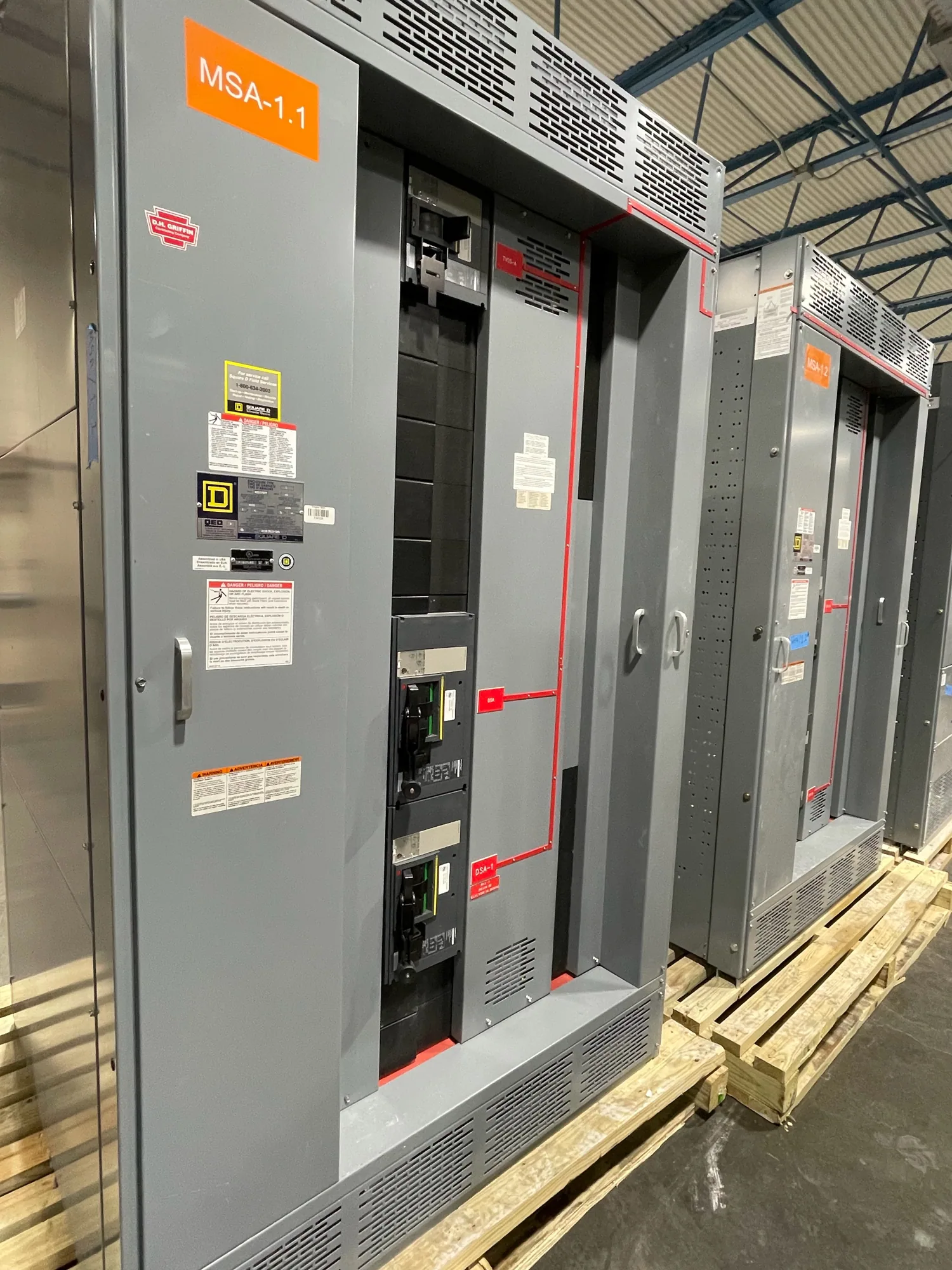
Bus design within a switchboard assembly
In a low-voltage switchboard, busbars form the conductive paths that connect incoming service equipment with distribution sections and outgoing feeders. Their design is not an isolated choice of metal or dimensions: it must align with the assembly’s specified current, protective devices, fault-duty requirements, physical layout and installation environment. A bus arrangement that suits one lineup cannot be assumed suitable for another.
For a new assembly, buyers should consider main, vertical and feeder bus as part of the complete switchboard specification. The responsible project engineer determines the system requirements and verifies that the proposed construction, devices, enclosure and connections work together. Switchboards are distinct from medium-voltage switchgear; this discussion concerns low-voltage switchboard bus design and does not establish a rating or compliance claim for any particular assembly.
Material and cross-section must match the application
Bus material and cross-section affect how the assembly carries current and manages heat, but larger or heavier bus is not automatically the right answer. The actual design depends on specified continuous current, arrangement, enclosure conditions, connection details and the applicable equipment design. Copper or aluminum may be considered where offered and suitable; the buyer should identify any material requirement rather than assume a default.
Provide the required service and feeder currents, including how loads are expected to operate, and identify any defined future capacity or spare provisions. Clarify whether the stated values are project requirements or preliminary estimates. The manufacturer and responsible engineer need to confirm the proposed construction against the complete specification. Do not select bus dimensions from a rule of thumb or a standalone ampacity table without checking the assembled equipment and its operating conditions.
Fault duty, bracing and protective devices
Available fault current and the required short-circuit or withstand performance are central to bus support and bracing. During a fault, electrical forces can impose substantial mechanical stress on bus conductors and their supports. The required design therefore relates to the specified fault conditions and duration, as well as the switchboard configuration and protective-device characteristics. A nominal current value alone does not define this requirement.
Buyers should provide the project’s documented fault-duty requirements and the information available about upstream protection. The responsible engineer must verify the system study, protective-device coordination and equipment ratings for the actual installation. Service breakers, feeder breakers, fuses and other devices can affect the design basis, but one device choice does not by itself establish that the full assembly is suitable. Confirm ratings, listing applicability and construction against the final design; do not infer them from a generic product description.
Temperature, joints and expansion
Temperature rise depends on more than bus cross-section. Current distribution, contact quality, enclosure layout, ambient conditions, ventilation and nearby heat sources can all matter to the assembled design. Specify known environmental conditions, including indoor or outdoor location where relevant, ambient temperature expectations, altitude if the project engineer identifies it as applicable, and exposure to dust, moisture or corrosive agents. The equipment design and any applicable evaluation should address the stated conditions.
Every bus joint is also a design and assembly consideration. The specification should identify required access or inspection expectations and any project-defined connection constraints. Thermal cycling can cause conductors and supports to expand or contract; the arrangement must accommodate movement as designed without compromising connections or clearances. Expansion provisions, joint construction and maintenance access are configuration-specific questions for engineering review, not details to settle from a generic diagram.
Automotive manufacturing: an illustrative design review
Consider a hypothetical automotive manufacturing facility planning a new low-voltage switchboard for production loads. No load values, fault current, ambient conditions, layout or utility characteristics are assumed here. The project team would first establish the intended service and feeder functions, load data, operating profile and required expansion capacity, then confirm the available fault-duty information and protective-device basis with its qualified electrical engineer.
Production environments may raise project-specific questions about dust, heat, vibration, washdown or corrosive exposure, but none should be presumed for a particular facility. The buyer should describe actual conditions and identify any constraints on lineup footprint, cable entry, access, future feeders and shutdown planning. Engineering review can then assess bus material, construction, bracing, joints and enclosure choices as a coordinated assembly rather than as independent selections.
Information to include in a bus specification
A useful request for proposal or equipment specification identifies system voltage, phase and frequency; service and feeder functions; required continuous-current values; fault-duty data and its source; protective-device requirements; and the intended equipment arrangement. Include one-line diagrams, available load schedules, wiring or control requirements, enclosure and environmental conditions, space limits, cable-entry preferences, and any required spare or future provisions. Mark preliminary information clearly so unresolved inputs are not mistaken for approved design criteria.
Also ask which bus material and configuration are proposed, how the specified fault-duty basis is addressed, and what documentation will be provided for review. Confirm which devices and accessories are included, which are excluded, and how the assembly’s ratings and any applicable listing will be verified for the actual design. UL 891 may apply to eligible low-voltage switchboards, but applicability and assembly listing must be confirmed for the specific equipment; it should not be presumed for every configuration.
Coordinate submittals before release
Before manufacturing release, compare the switchboard submittal with the approved one-line, load information, fault-duty basis, room layout and installation requirements. Resolve differences in bus arrangement, feeder count, device selections, access clearances, cable routing and future provisions in writing. The project engineer should approve design assumptions and confirm any required studies or standards review; equipment-specific testing, ratings, listing and delivery details also require confirmation against the final specification.
South Carolina Switchgear Builders manufactures new switchboards to specification, with US-built equipment and all-American components, and ships nationwide. Availability and actual lead times depend on the order and must be confirmed. Provide complete project documents and identify open engineering questions early so the proposed assembly can be reviewed against the application. Installation, testing and maintenance should be performed by qualified personnel following applicable safety procedures.