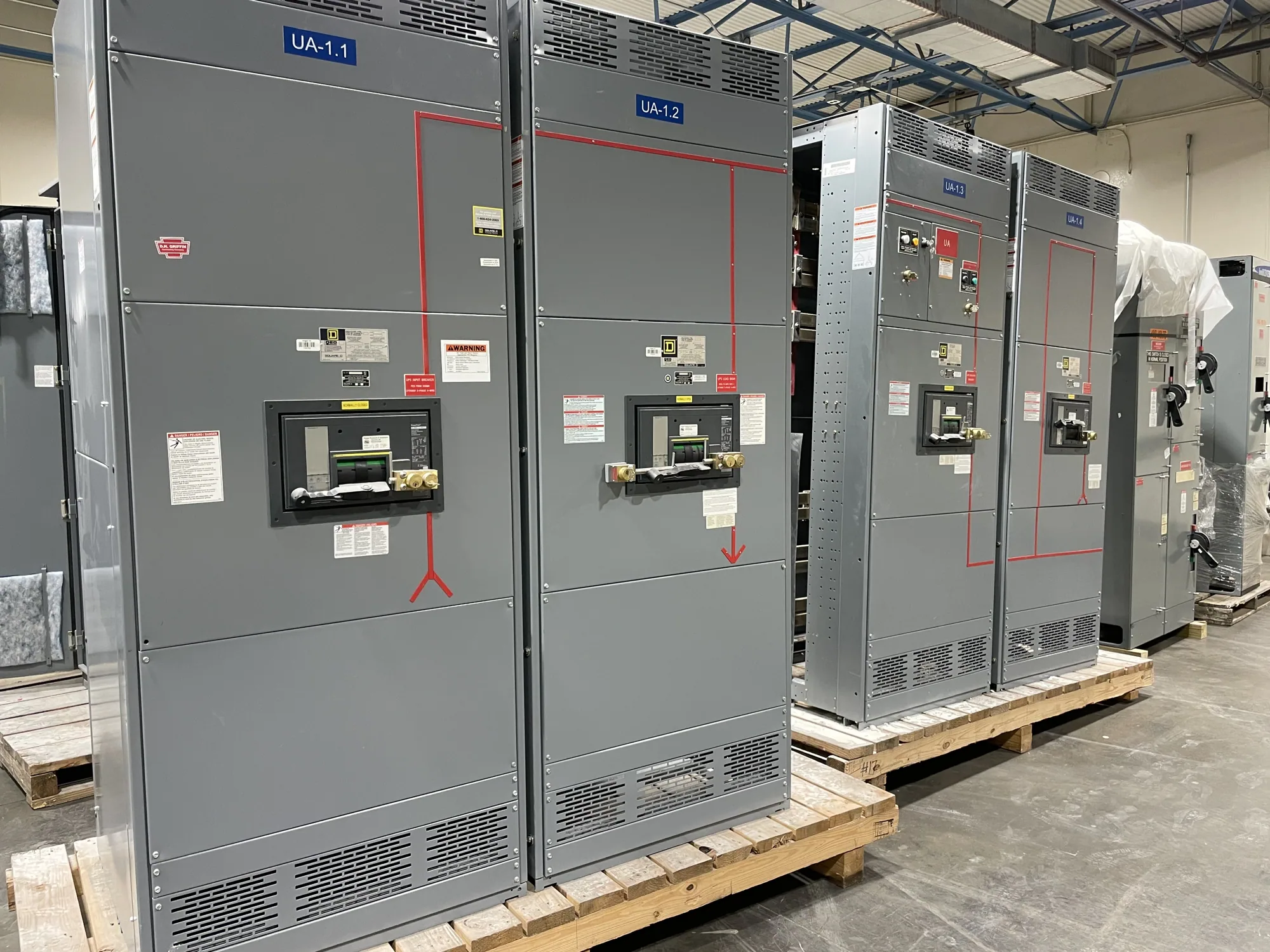
Where coordination matters in a switchboard
In low-voltage distribution, selective coordination concerns how protective devices respond when a fault occurs downstream. The design objective is to have the device nearest the fault interrupt it while upstream devices remain closed, within the specified operating range and conditions. For a switchboard, that relationship may involve the service disconnect, feeder devices, and downstream equipment. It is not established by choosing a switchboard enclosure or a breaker family alone.
Requirements depend on the project, system arrangement, and applicable codes or owner criteria. The responsible electrical engineer should identify the circuits and fault conditions included in the coordination study and confirm the required range. Do not assume every possible fault or every device combination can be coordinated. The specification should state the intended scope and identify any exceptions, limits, or conditions that need review.
How device choices shape the assembly
Service and feeder protective devices must be evaluated as a connected system. Their time-current behavior, available fault current, settings, and operating characteristics affect whether coordination is achievable. A change to an upstream device, feeder rating, or downstream equipment can alter the analysis. The project engineer should assess the actual device data and system conditions rather than rely on a general statement that devices are selective.
Coordination goals can also influence switchboard layout and configuration. Device type, frame and trip choices, compartment arrangement, conductor paths, and access needs may affect the assembly design. Fault-current ratings and short-circuit withstand requirements are separate checks: satisfying a coordination objective does not by itself establish that equipment is suitable for the available fault current. Confirm all ratings and configurations against the project specification and proposed equipment.
Balancing continuity and protection
Keeping an upstream device closed can help limit an interruption to the affected portion of a distribution system. However, coordination must be considered alongside protection of conductors and equipment, clearing time, and the project's safety and operating priorities. Extending a device's operating delay to improve selectivity may create other design questions. The engineer responsible for the system must determine acceptable settings and verify the consequences for the full installation.
There may be tradeoffs among device options, physical space, and the range over which selectivity is required. A design that coordinates under one set of fault conditions may not do so under another. Ask the engineer to document the basis of the evaluation, including device combinations, settings, and limits. Then make sure the switchboard specification and approved submittal identify equipment consistent with that basis.
Illustrative manufacturing scenario
Consider an automotive manufacturing facility planning a new low-voltage switchboard to serve production areas and building loads. No system voltage beyond the stated low-voltage class, fault current, device ratings, or coordination results are assumed here. The project team may want a fault on one production feeder to avoid unnecessarily interrupting unrelated loads. Whether that is attainable depends on the actual one-line diagram, upstream source, protective devices, and defined coordination range.
The engineer would need to evaluate the system conditions and device information, then determine whether the proposed service and feeder choices meet project requirements. Production continuity cannot be promised from a switchboard description alone. If operating priorities call for different treatment of selected loads, identify that early so the engineer can assess the distribution arrangement and the manufacturer can review the specified assembly configuration.
Information to provide for a useful review
When requesting a switchboard proposal, provide the current one-line diagram, system voltage and phase, source information, available fault-current data, and the intended service and feeder schedule. Identify the coordination-study scope, required operating range, known protective-device types and settings, and any owner or authority requirements. Include physical constraints, incoming and outgoing conductor details, environment, and the requested enclosure rating so layout and configuration can be evaluated together.
- State which upstream and downstream devices are included in the coordination objective.
- Provide the engineer's documented device selections, settings, and study assumptions when available.
- Identify required fault ratings, metering, controls, access, and any project-specific exclusions.
- Ask which ratings, listing, testing, and standards applicability must be confirmed for the proposed assembly.
Submittals, verification, and next steps
Before release, coordinate the approved one-line diagram and equipment schedule with the switchboard submittal. Confirm that device designations, ratings, accessories, and stated options match the engineer's evaluated configuration. Ask how any requested changes will be reviewed; substituting a device or revising settings can affect the coordination basis. Assembly listing and standards applicability are specific to the proposed design and must be confirmed, not presumed.
South Carolina Switchgear Builders manufactures new switchboards to specification, with US-built equipment and all-American components, and ships nationwide. Availability and actual lead times depend on the order and require confirmation. Provide complete project documents and identify open engineering questions when requesting a proposal. A qualified engineer should perform the coordination analysis and applicable design review; installation, testing, and maintenance belong to qualified personnel following applicable safety procedures.