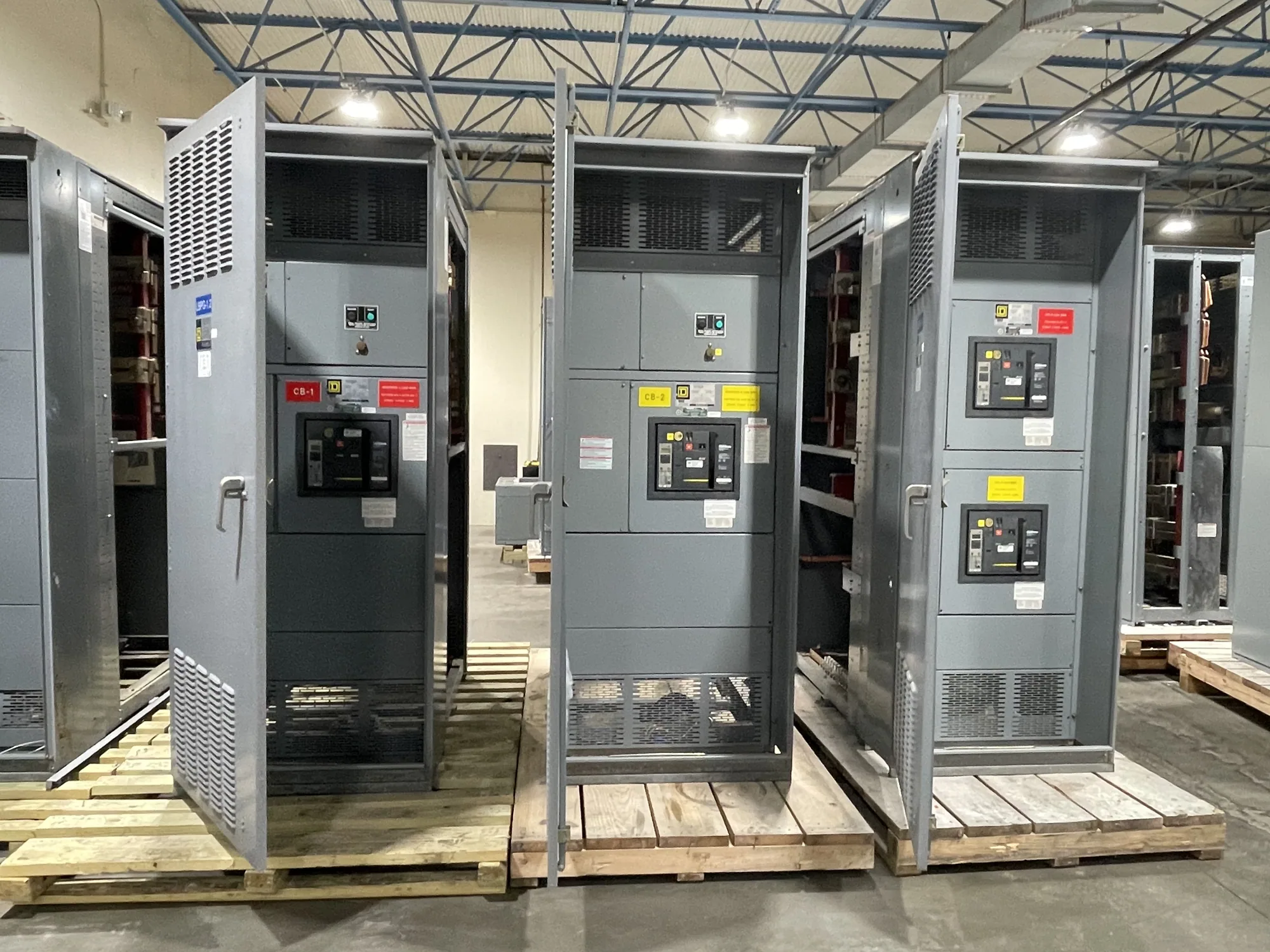
Apply ratings to the complete distribution path
In a low-voltage switchboard, short-circuit ratings are not a single interchangeable number. The available fault current is the prospective current at a particular point in the electrical system. Protective devices have interrupting ratings, while the switchboard assembly has a short-circuit current rating or withstand rating established for its specified configuration. These values describe different aspects of a fault and must be assessed together.
For service and feeder distribution, the relevant comparison begins with the available fault current where the equipment will be installed. The engineer evaluates the source and system conditions, then specifies devices and an assembly suitable for the calculated conditions. Downstream locations may have different available fault current, so the assessment belongs to the system layout, not simply to a building-wide label.
Distinguish device interrupting capacity from assembly withstand
A circuit breaker or fuse must have an interrupting rating appropriate for the available fault current at its location, subject to the engineered design and applicable requirements. The switchboard assembly must also have a suitable rating for the proposed arrangement. A device’s interrupting capacity does not by itself establish the rating of the enclosure, bus, connections, or complete assembly.
Some designs may rely on a tested, specified combination of upstream and downstream protective devices. Any such series-rated or otherwise conditional arrangement requires confirmation for the exact devices and assembly; do not assume that different breakers can be substituted while retaining the stated rating. The project documents should identify the conditions, device types, and limits that support the proposed design.
Coordinate service and feeder choices with the layout
At the service section, source characteristics and upstream protection influence the available fault current and device selection. Feeder sections then distribute power to loads or other panels, with protection selected for each branch’s design conditions. Bus configuration, section arrangement, device frame and trip options, and the physical space required for the specified equipment can all affect the switchboard layout. Higher or conditional rating choices may change the acceptable device combinations and assembly configuration.
Ask the responsible engineer to identify the fault-current value at the switchboard and the basis for it, including relevant source and transformer information. Clarify whether the study addresses normal and alternate operating configurations where applicable. Confirm that the requested service and feeder devices, trip settings, and any specified protective-device coordination are compatible with the equipment proposal. These decisions should be resolved before the design is treated as final.
Consider an automotive manufacturing example
Imagine an automotive manufacturing project with a new low-voltage service switchboard supplying production-area feeders. No fault-current values, transformer data, or device selections are assumed here. The engineer would need to determine available fault current at the switchboard and at relevant downstream points, accounting for the project’s actual source and distribution arrangement. Production loads and planned system configurations may inform the design, but they do not substitute for a calculation.
The team can then compare the calculated conditions with interrupting ratings for proposed protective devices and the documented rating of the complete switchboard assembly. If a change to source equipment, feeder arrangement, or protective devices is considered, ask whether the fault study and equipment rating review must be updated. A qualified engineer should perform the calculation and review the applicable standards; the manufacturer can evaluate the specified equipment configuration against the project requirements.
Provide complete, equipment-specific information
For a useful equipment review, provide nominal system voltage and phase, service or feeder function, one-line diagram, source and transformer details available to the project team, and the calculated available fault current at the proposed switchboard. Include the calculation basis and study date if known, upstream protective-device make and type, requested switchboard sections, feeder device schedule, and any required alternate-source or tie arrangements.
Also state the required assembly rating and how it must be demonstrated, if the engineer has established that requirement. Identify requested device interrupting ratings, any conditional or series-rating basis, enclosure and access constraints, incoming conductor approach, and project documentation needs. Ask which combinations are included in the proposed assembly and which devices, operating modes, or later modifications fall outside the reviewed configuration.
Review documentation before release
Before approving submittals, compare the equipment schedule, one-line diagram, fault-current study, and proposed switchboard documents line by line. Check that the specified ratings refer to the same system voltage and equipment arrangement, and that service and feeder device descriptions match. Resolve discrepancies with the project engineer and manufacturer rather than inferring an acceptable rating from a component nameplate or an unrelated assembly.
For new switchboards, South Carolina Switchgear Builders can review project specifications and provide equipment custom to specification. Listing, testing, ratings, availability, and delivery timing depend on the actual design and order and should be confirmed for the proposed assembly. Submit the latest project documents and identify unresolved rating questions early; that gives the engineering team and manufacturer a clear basis for coordinating a suitable equipment proposal.