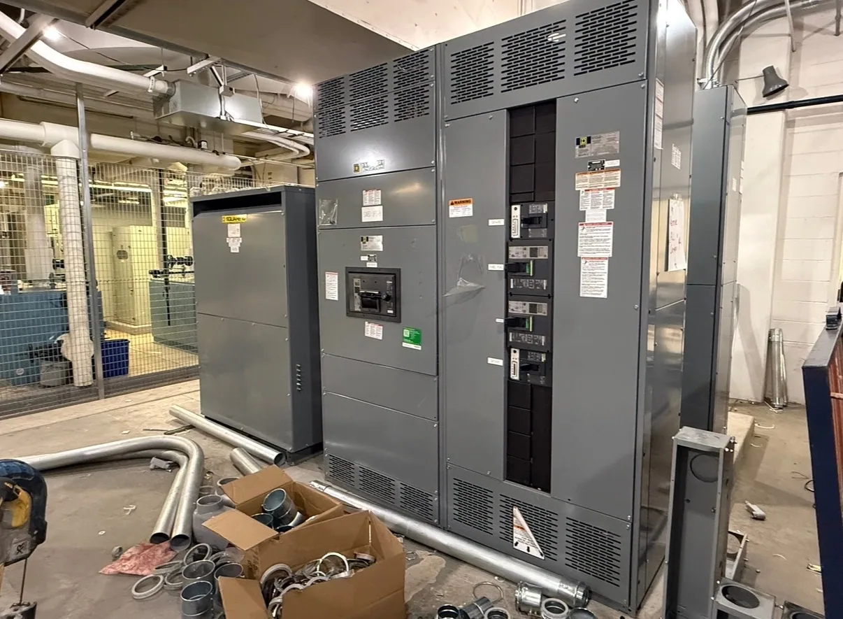
Start with the facility and project scope
Planning new switchgear for a facility in Sumter begins with the job’s electrical requirements, not a catalog description. A manufacturing expansion, process-system upgrade, or institutional facility renewal may have very different load profiles and operating priorities. These are useful planning scenarios, not assumptions about any specific local site. Establish whether the project is new construction, a capacity addition, or replacement equipment serving existing loads.
Define what the equipment must control and distribute, where it connects to the existing system, and which loads must remain available during construction. The project engineer should establish system voltage, available fault-current information, grounding approach, and the required arrangement of incoming and outgoing circuits. A clear scope helps the manufacturer evaluate a design that fits the application rather than relying on incomplete assumptions.
Document feeders, loads, and site conditions
For a replacement or expansion, assemble current one-line diagrams, equipment schedules, feeder information, and available records for the existing lineup. Identify circuit functions, connected loads, conductor details, and any known constraints on the electrical room or equipment access. If records are incomplete, flag what needs field verification by qualified personnel instead of treating an old drawing as definitive.
List normal operating current and expected load behavior for each relevant feeder, including motor starting or other significant load changes when applicable. Continuous-current needs, bus and device ratings, enclosure arrangement, and operating-temperature conditions must be evaluated for the actual design and installation environment. Ambient conditions, ventilation, grouping, and project-specific configuration may affect the responsible engineer’s selection; do not infer a rating from one nameplate value alone.
Consider motor control as a distinct requirement
Where a project includes numerous process motors, evaluate whether a motor control center (MCC) belongs in the distribution plan. For a hypothetical automotive manufacturing project, the review might begin by grouping motors by process area, documenting each motor’s electrical data and control needs, and identifying which functions require coordinated operation. This example illustrates a planning method and does not describe an installed project.
An MCC is not interchangeable with every switchgear or switchboard arrangement. The appropriate equipment depends on the system architecture, motor-control functions, available space, operating practices, and the interface with upstream distribution. Ask the project engineer to determine whether motor starters, drives, protective devices, control power, communications, or future spaces are required. Confirm how the selected equipment coordinates with the facility’s protection and control scheme.
Plan replacement and cutover deliberately
When new equipment replaces an existing lineup, document the required connections and the physical conditions that can shape the design: room dimensions, working clearances, cable entry and exit, access routes, and the location of adjacent equipment. Confirm which existing feeders and loads must be transferred, whether the new lineup can match the intended interfaces, and what site modifications may be necessary. These details should be checked against drawings and verified conditions.
Develop a cutover plan with the facility team and qualified electrical professionals. Identify outage windows, temporary operating arrangements if needed, sequencing, inspection responsibilities, and the point at which each load can be returned to service. New equipment must be installed, tested, and maintained by qualified personnel following applicable safety procedures. Do not assume that a proposed layout or delivery date by itself resolves shutdown or installation risks.
Prepare a useful request for quotation
A strong request for quotation (RFQ) includes the project location, application, required equipment type, system voltage, one-line diagram, load and feeder schedules, and the requested ratings and configuration for engineering review. Include available fault-current and grounding information, enclosure and environmental requirements, connection preferences, control requirements, and any applicable project specifications. Mark uncertain or pending information clearly so it can be resolved before the design is finalized.
Also identify the required submittal information, review milestones, requested shipment window, delivery constraints, and receiving arrangements. Share equipment-room access limitations and any known restrictions on unloading or movement to the installation area. The manufacturer can assess the request more effectively when the scope separates confirmed requirements from items awaiting the engineer’s decision.
Coordinate specifications, availability, and delivery
South Carolina Switchgear Builders manufactures new equipment in the United States, uses all-American components, offers custom-to-specification equipment, and ships nationwide. Short lead times may be available, but actual availability and timing depend on the order and must be confirmed. Provide the project schedule early, then confirm the proposed configuration, submittal and approval process, manufacturing schedule, shipping plan, and delivery date for the specific order.
Before release, the project team should verify that the offered design addresses the approved drawings and specification, including applicable ratings, devices, and any required listing or testing. UL 891 applicability is limited to eligible low-voltage switchboards, and the specific assembly’s listing must be verified; it is not a blanket claim for all equipment. Keep the engineer, purchasing team, manufacturer, and receiving site aligned on changes and open decisions. Clear documentation and timely confirmation create a more dependable path from specification through delivery to qualified installation.