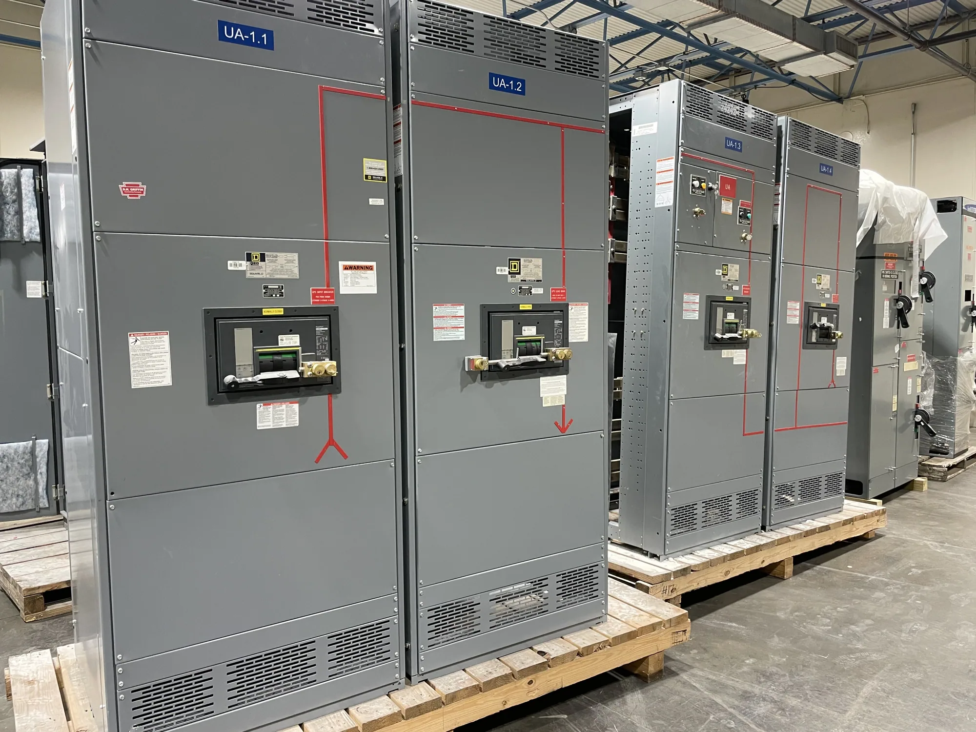
Where indoor switchgear fits in a data center
In a data center, indoor switchgear is part of a larger electrical system serving IT equipment, cooling, lighting, and other building loads. Its exact role depends on the one-line diagram and project architecture: equipment may receive power from utility, generator, or other sources and distribute it to downstream systems. A manufacturer can build new equipment to a confirmed specification, but the project engineer defines the system and its interfaces.
High-density IT demand makes capacity planning especially consequential. Cooling demand, future growth, and the operating strategy influence how distribution is divided and how much capacity is installed at each stage. Redundancy goals also affect source and bus arrangements. Avoid selecting equipment from a general description such as “data center rated”; establish the actual electrical, operational, and space requirements for the intended installation.
Coordinate sources, redundancy, and phases
Document each normal and alternate source and show how the system is intended to transfer or isolate power. The design team should identify the switching devices, interlocks, controls, and protection interfaces required by the project, along with responsibility for each interface. Generator operation and any other backup strategy must be reflected in the approved system design; do not assume a particular transfer scheme or operating sequence from the facility type alone.
Capacity phasing creates a tradeoff between installing for anticipated growth and matching equipment to near-term demand. Consider whether future sections, feeders, or loads are part of the initial scope, and whether expansion can occur without disrupting critical operations. Define the phase-one configuration and all known future interfaces before requesting a quote. The manufacturer can confirm what can be built to the submitted scope, while system performance and expansion strategy remain matters for the responsible design team.
Resolve voltage and equipment ratings
Provide the nominal system voltage and the equipment class required by the design. The project engineer should confirm the system configuration, grounding arrangement, frequency, and applicable fault-duty requirements, then specify the equipment maximum voltage and insulation requirements where relevant. Nominal voltage alone does not fully define an assembly. Do not infer ratings from a previous facility or from a broad label such as indoor switchgear.
Identify whether the project calls for low-voltage switchboards or medium-voltage switchgear; these are not interchangeable product descriptions. For a 480 V class application, specify the required low-voltage assembly and its duties. For 5 kV or 15 kV class applications, identify the medium-voltage equipment requirements. The design team must confirm ratings, protection coordination, listing or other requested standards, and the exact configuration for each assembly.
Fit the equipment to the room and installation route
Room planning should account for equipment dimensions, access for assembly placement, working clearances, doors, corridors, and the intended maintenance approach. Confirm these constraints against the building layout and the equipment configuration before release. Also identify floor or structural limitations, environmental conditions, ventilation provisions, and any restrictions on moving equipment through the site. These details can change lineup arrangement and delivery coordination.
Heat rejection and room conditions deserve explicit review rather than assumption. Ask the design team to establish acceptable environmental conditions and how room cooling addresses the equipment and surrounding electrical loads. Clarify whether the equipment must be installed in a particular orientation or arranged to preserve access to rear or side compartments. Installation, testing, and maintenance should be planned and performed by qualified personnel under applicable safety procedures.
Plan monitoring and maintainability
List the measurements, alarms, and status points the facility needs, and specify how they should interface with the site monitoring or control system. Define communication requirements and responsibility for configuration and integration. “Monitoring ready” is not a complete specification: the buyer should identify desired points, protocols if selected by the project, and the party responsible for end-to-end verification.
Maintainability also depends on how devices can be inspected, isolated, and serviced within the room and operating plan. Identify required access, labeling, documentation, and any project-specific maintenance provisions. Discuss outage constraints with the owner and engineer early, especially where the facility will be occupied or operating during later construction. A manufacturer’s equipment scope should be distinguished from field installation, commissioning, system studies, and ongoing maintenance.
Prepare a useful purchasing package
For a focused quotation, provide the latest one-line diagram, equipment schedule, voltage and rating requirements, source and tie arrangement, and the specified protection and control scope. Include room dimensions, access route, environmental conditions, monitoring interfaces, phasing requirements, and requested standards or listing criteria. State what is excluded or supplied by others, and flag unresolved design decisions rather than leaving them implicit.
South Carolina Switchgear Builders manufactures new switchgear and switchboards to specification, with US-built equipment, all-American components, and nationwide shipping. Availability and actual lead times depend on the order and must be confirmed. Before procurement, align the approved drawings, ratings, interfaces, physical constraints, and delivery plan among the owner, engineer, electrical contractor, and manufacturer. That coordination gives the project team a clear basis for evaluating the proposed equipment and preparing the site.