Distribution decisions around the production line
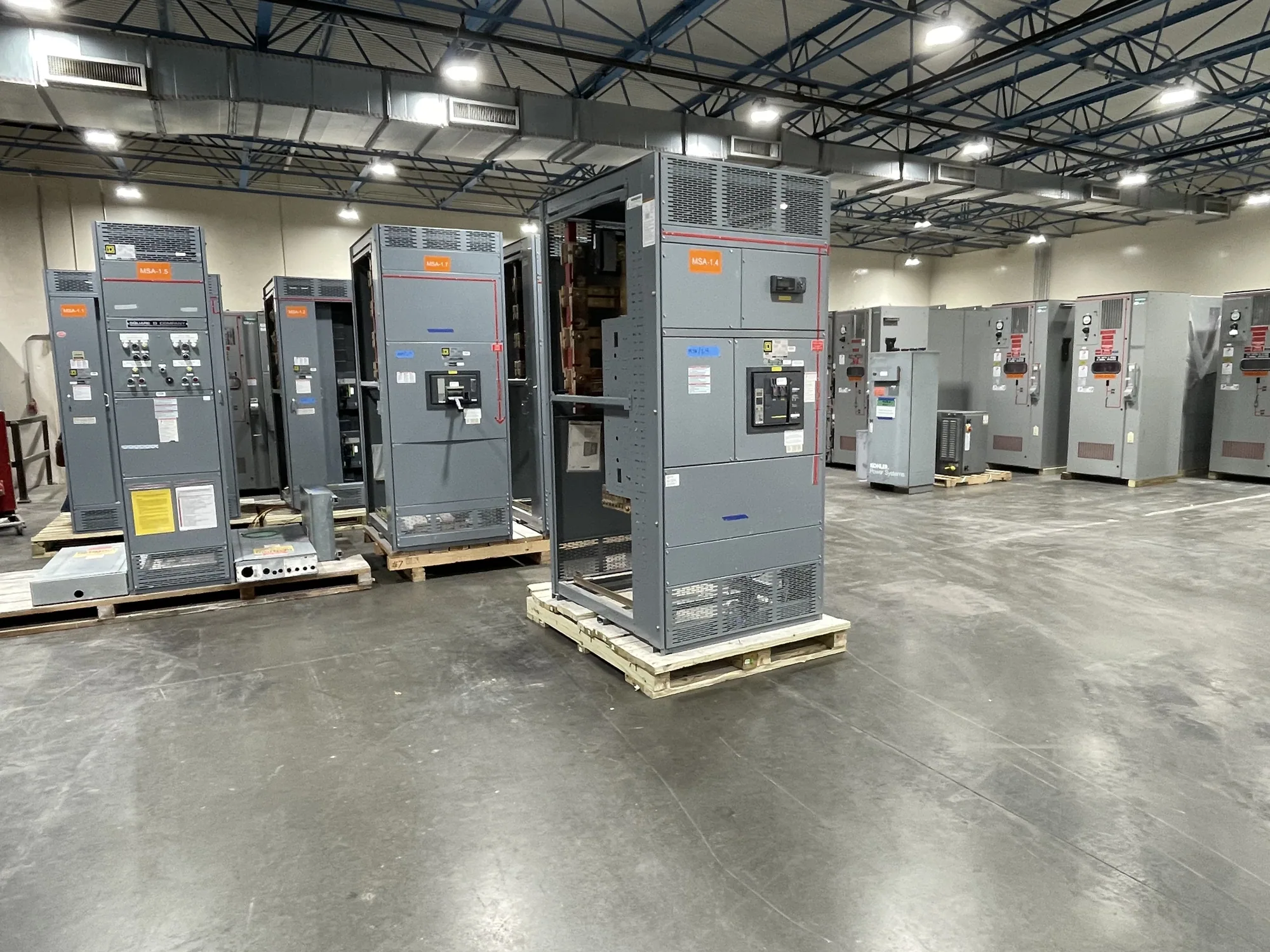
Automotive manufacturing facilities can combine assembly lines, robotic cells, conveyors, welders, paint operations, material handling, and building services. A low-voltage switchgear assembly may receive power from an upstream source and distribute it through protective devices to downstream equipment. Its role and boundaries depend on the facility's one-line diagram and project scope; it should not be treated as a universal solution for every production load.
For a new line or an upgrade, start by mapping which loads must operate together, which can be shed, and what happens when a feeder is unavailable. Production teams may have different priorities from facilities or maintenance teams. A proposed arrangement should reflect those operating needs without assuming that every load has the same duty cycle, starting behavior, or tolerance for an interruption.
Fault ratings and protective-device coordination
Interrupting capability and assembly withstand capability address different parts of a fault-duty review. The project engineer should establish available fault current at the proposed connection and coordinate the required ratings with the protective-device selection and upstream system. Do not select an assembly by normal load current alone: fault conditions, source characteristics, and the specific design all matter, and the applicable values must be confirmed for the project.
Automotive sites may have multiple sources, transformers, generators, or other configuration-dependent interfaces. If a project includes alternate feeds or future tie arrangements, provide their intended operating states for review rather than assuming every source can operate in every combination. The responsible engineer should resolve coordination, protection, and any applicable study requirements. The manufacturer can build to a confirmed specification; it does not replace the project engineer's system design.
Production continuity, feeder separation, and access
Staged outages can influence how a new assembly connects to existing distribution. Identify the allowable outage windows, the loads that must remain available, and any planned phases of construction. Feeder segregation may help organize circuits by production area or operating priority, but the right arrangement depends on the electrical design, physical layout, and maintenance procedures. Confirm which boundaries belong in the switchgear scope and which are downstream.
Maintainability is also a layout question. Review working clearances, access to operating handles and compartments, cable entry and exit, and the path for bringing equipment into the electrical room. Room dimensions, ceiling height, doorways, adjacent equipment, and the sequence of installation can constrain an otherwise suitable arrangement. Qualified project personnel should determine access and safety requirements; do not assume that a compact footprint automatically makes an assembly easier to service.
Continuous current and operating conditions
Continuous current rating should be considered alongside the expected load profile, bus rating, protective-device ratings, and how the assembly will be used. Share normal and maximum operating loads, diversity assumptions, known motor starting or cycling conditions, and any planned spare capacity. The engineer should identify which values govern the specification and verify that the selected bus and devices suit the intended operating conditions.
Ambient temperature, enclosure arrangement, ventilation, altitude, conductor configuration, and other design conditions may affect equipment selection or rating. Do not presume a rating remains unchanged under every installation condition. Provide the expected environment and installation details, then ask which assumptions apply to the proposed design and whether any derating or other adjustment is needed. Confirm ratings and operating limits against the actual assembly documentation before procurement and installation.
Plan for expansion without overbuilding
Automotive programs can change as production capacity, equipment, and process layouts evolve. Describe known phases, likely future feeders, and the space reserved for later work. Distinguish a defined future requirement from a general desire for flexibility: reserved provisions, physical space, and connected capacity are not interchangeable. The project engineer should determine what can be incorporated safely and practically in the initial design.
Expansion provisions can affect lineup length, room planning, bus selection, and the way incoming and outgoing connections are arranged. Ask how a future change would interface with the initial assembly and what work would require an outage. Avoid assuming that an empty space or spare device position guarantees future compatibility; the intended scope and design conditions should be documented and confirmed.
Information to include in a manufacturer RFQ
- Provide the one-line diagram, nominal system voltage, source details, and available fault-current information at the connection point.
- List load groups, expected continuous currents, motor-related operating information, feeder quantities, and any required separation by production area.
- State the required interrupting and withstand ratings, protective-device preferences, and coordination constraints as established by the responsible engineer.
- Include room dimensions, access and cable-entry constraints, environmental conditions, planned outage phases, and known expansion requirements.
- Identify requested documentation, project schedule needs, delivery destination, and any standards or listing requirements that must be evaluated for the specific assembly.
A complete RFQ gives the manufacturer a clearer basis to identify scope questions and prepare a project-specific offer. If information is preliminary, label assumptions and open decisions rather than presenting them as confirmed design inputs. Availability and lead time depend on the order and must be confirmed; delivery dates, ratings, testing, listing, and standards applicability also require review against the actual specification and equipment.
Coordinate scope from design through delivery
South Carolina Switchgear Builders manufactures new low-voltage switchgear to specification, with US-built equipment and all-American components, and ships nationwide. Discuss the required configuration, documentation, and schedule during quotation; short lead times may be available, but the actual lead time and delivery date must be confirmed for the order. For eligible low-voltage switchboards, UL 891 applicability and assembly listing must be verified for the specific design; it should not be assumed for every assembly.
Keep responsibilities clear as the project advances. The project engineer establishes system requirements and approves the design basis; the manufacturer supplies equipment to the confirmed scope. Installation, field testing, commissioning, and maintenance are separate project activities for qualified personnel following applicable safety procedures. Align submittal review, connection details, shipping arrangements, site readiness, and outage planning early so the new distribution equipment can be coordinated with the production schedule and facility interfaces.