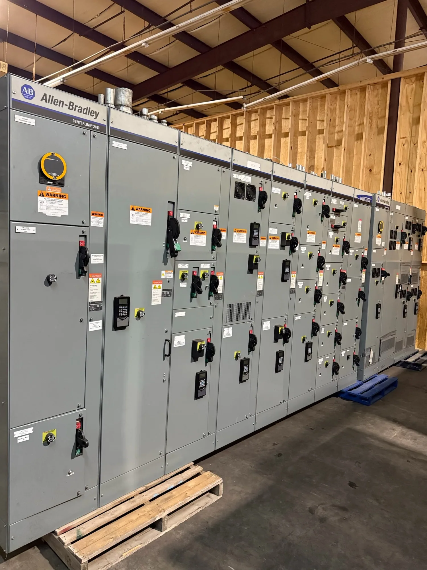
Where metal-clad switchgear fits in a process plant
A chemical processing facility may distribute power from a utility or on-site source to transformers, large motors, and downstream distribution equipment. Where the project calls for medium-voltage metal-clad switchgear, it can provide a lineup for switching and protection at the specified system voltage. The right scope depends on the one-line diagram, load profile, operating plan, and responsible engineer’s design—not on the industry label alone.
Start by identifying which feeders the lineup must serve and what each one supplies: process motors, substations, plant auxiliaries, or other defined loads. Note whether the work is a new installation, an expansion, or a replacement, and explain how the proposed equipment connects to existing systems. This context helps the manufacturer evaluate the specified configuration and interfaces without assuming responsibility for plant electrical design.
Account for process hazards and equipment location
Process areas can include locations subject to hazardous-area classification, corrosive agents, heat, dust, moisture, or other environmental conditions. Metal-clad construction does not, by itself, make switchgear suitable for a classified location or every plant environment. The project team should provide the area classification and environmental requirements, then have the responsible engineer determine where the lineup belongs and what installation conditions apply.
In some layouts, the switchgear may be located outside a classified or otherwise unsuitable process area, with feeders routed to loads in that area. That choice affects cable paths, terminations, control circuits, building arrangements, and access for operation and maintenance. Confirm the location, room conditions, clearances, access restrictions, and relevant interface points before equipment configuration is finalized. Site-specific hazard and code determinations remain with the qualified project professionals.
Specify voltage and system configuration carefully
Provide the nominal system voltage and the project’s required equipment voltage class as separate, explicit items. Also identify frequency, phase, grounding method, source arrangement, and any operating configurations shown in the design. The responsible engineer should confirm that the proposed equipment’s voltage and insulation characteristics suit the system and applicable specification. Do not select equipment from a nominal voltage label alone or infer an acceptable rating from a similar installation.
Describe normal and alternate sources, bus arrangement, tie operation, and any limits on paralleling or transfer. Include the available fault-current information and the assumptions or study references supplied by the project engineer. Required interrupting and withstand capabilities depend on the actual system and design basis, so they need project-specific confirmation. If system data is preliminary, identify it as preliminary and establish how revisions will be communicated before approval.
Coordinate protection, motors, and operating needs
Large process motors can shape feeder protection, starting strategy, and plant operating sequences. Provide motor data available for the project, including ratings, starting method, duty, and any required operating or interlocking logic. Protection settings and device selections must be coordinated with the system study and the engineer’s criteria; they should not be guessed from a general application description. Clarify which protection functions, metering, controls, and communications are required at each feeder.
Ask how the specified compartments, removable devices, and access arrangements support the intended operating and maintenance plan. Review permitted switching sequences, isolation points, interlocks, control-power sources, and connections to plant systems. Confirm which functions are part of the supplied assembly and which are provided elsewhere. Outage windows and process continuity constraints may affect the project schedule and connection plan, but do not substitute for approved procedures or qualified personnel.
Resolve the practical trade-offs early
A more segmented arrangement may help define equipment compartments and service interfaces, while the lineup’s footprint, cable access, and operating clearances must still fit the room and installation plan. Removable devices may support the specified maintenance approach, but their value depends on how the facility plans to isolate equipment, manage outages, and maintain compatible spares. Compare options against documented operating needs rather than assuming that one construction choice suits every process plant.
Likewise, indoor placement, environmental provisions, control interfaces, and future feeder space can influence configuration and cost. State which conditions are known and which remain open. Ask the design team to resolve uncertain environmental exposure, expansion allowance, and integration requirements before procurement documents are frozen. Product details, ratings, availability, testing, and any applicable listing must be confirmed for the specific proposed design and supplied equipment.
Prepare a useful purchasing package
For a clear quotation request, assemble the current one-line diagram, equipment schedule, voltage and system data, feeder and motor information, fault-study basis, protection requirements, control diagrams, and applicable project specifications. Add the required environmental conditions, area-classification boundaries, room layout, cable-entry preferences, access constraints, and target delivery needs. Identify deviations, options, open engineering decisions, and the person authorized to resolve technical questions.
- Define lineup scope, source and feeder arrangement, and connection boundaries.
- Provide confirmed ratings and clearly mark any preliminary system data.
- List protection, metering, control, communication, and interlocking interfaces.
- Document site conditions, equipment location, access, and outage constraints.
- State required submittals, review milestones, and coordination responsibilities.
Coordinate supply with the project team
South Carolina Switchgear Builders manufactures new switchgear to specification, with US-built equipment and all-American components, and ships nationwide. Short lead times may be available, but actual availability and delivery timing depend on the order and must be confirmed. The purchase scope should identify the configuration, required documentation, review process, and delivery destination so both parties can resolve gaps before release.
Manufacturer supply is distinct from project engineering, hazard classification, installation, field testing, commissioning, and maintenance. Confirm in writing who is responsible for each activity and for interfaces with transformers, cables, protection systems, and plant controls. Installation and testing should be performed by qualified personnel under applicable safety procedures. With system data, process constraints, and responsibilities clearly defined, the project team can evaluate a configuration suited to the facility’s documented requirements.