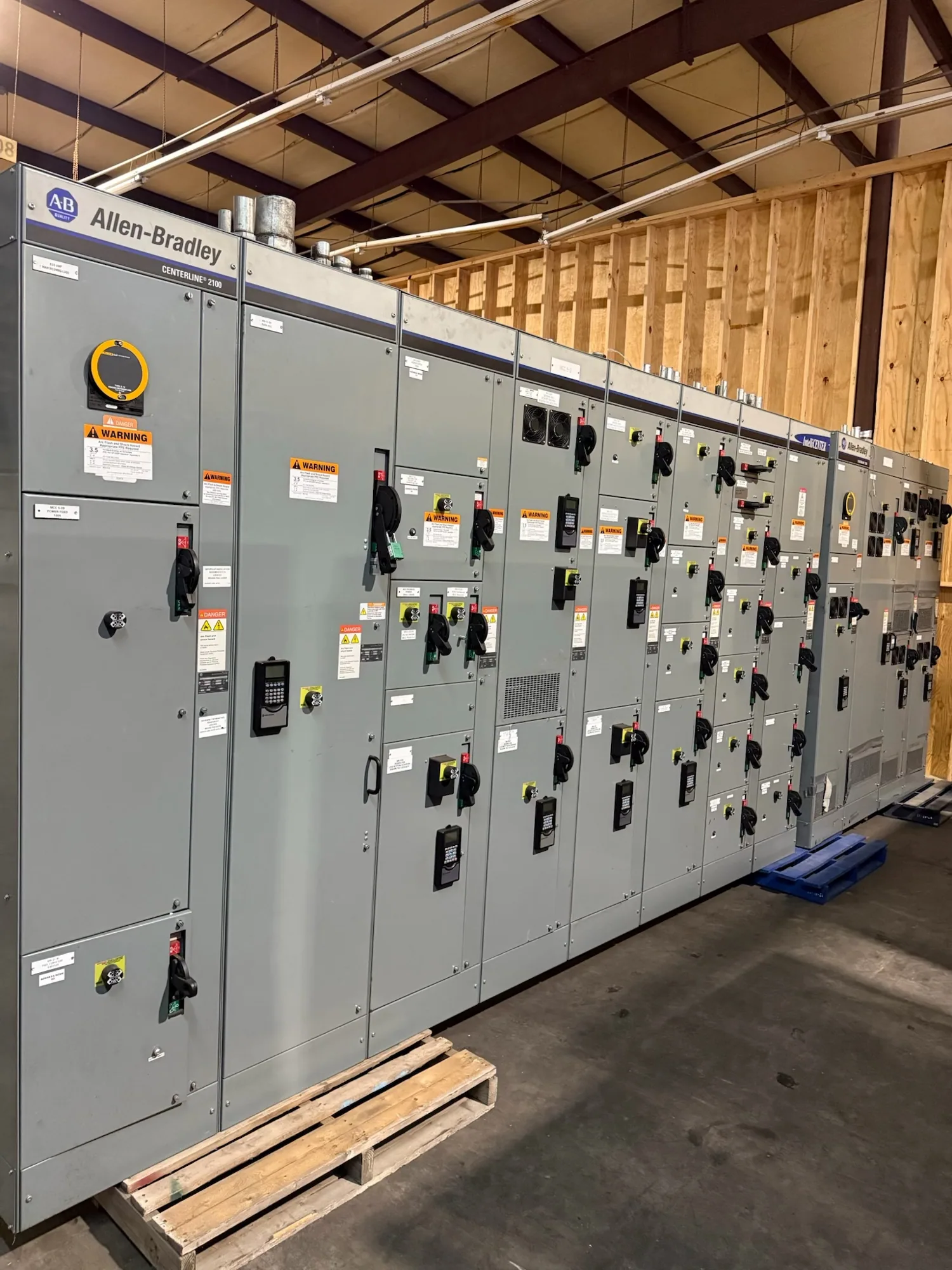
Where low-voltage switchgear fits in a data center
In a data center, low-voltage switchgear can serve as a distribution point between upstream sources and downstream loads, subject to the facility’s one-line design. Those loads may include IT power paths, cooling equipment, pumps, and other building systems. A hypothetical expansion illustrates the challenge: new server capacity may increase electrical demand while cooling and backup arrangements also change. The assembly must be specified for its actual role, not simply selected by facility type.
Redundancy strategies influence the required arrangement. A project may have multiple utility, generator, or other sources, but the equipment design depends on how those sources are connected, controlled, and isolated. The responsible engineer should define the intended operating modes, transfer or paralleling approach where applicable, and which loads each section serves. This helps the manufacturer understand the required lineup and interfaces without assuming a particular topology or promising a facility-level redundancy outcome.
Coordinate loads, sources and future phases
Begin with a load schedule that distinguishes existing loads, the new IT capacity, cooling demand, and planned future phases. Identify which loads are continuous or operationally critical as the project engineer determines, and note expected simultaneous operation. Avoid relying only on a broad facility capacity figure: equipment sections, feeder quantities, and protective-device requirements follow the project’s actual distribution plan. Ask the engineer to reconcile projected growth with the initial installation so expansion does not compromise the specified design.
Source information is equally important. Provide the one-line diagram and describe the available sources, their connections, and the intended sequence of operation. Where generators, transfer equipment, or ties affect the switchgear, clarify their boundaries and control interfaces. Existing equipment may constrain the new assembly’s connection points or outage window. The project team should identify those conditions early; the manufacturer can review the specified equipment scope, but site engineering and system coordination remain project responsibilities.
Specify ratings from the system study
For each incoming and outgoing circuit, the design team should establish the applicable nominal system voltage and the equipment voltage class, then specify the required insulation and related design details. Do not treat a nominal voltage alone as a complete equipment specification. The responsible engineer should confirm how the system is grounded and configured, and identify any requirements that affect the assembly. South Carolina Switchgear Builders supplies new equipment custom to specification; project-specific ratings require confirmation against the actual design.
Interrupting and withstand requirements must be coordinated with the available fault-current information and protective-device scheme. Ask the engineer to provide the applicable study values and identify the conditions and locations they represent. The selected devices and assembly must match the confirmed requirements; do not infer suitability from a product category or an assumed rating. Listing, testing, ratings, and standards are specific to the offered configuration and need to be verified for the actual equipment.
Balance maintainability with space and access
Data center electrical rooms can be constrained by building geometry, adjacent equipment, cable routing, and required working and service access. Provide room plans, equipment location, preferred cable entry and exit directions, and known obstructions. Ask the design team to verify clearances and service access under applicable requirements. A compact footprint may appear attractive, but the layout also needs to accommodate the specified connections, operation, and maintenance approach without creating unreviewed field modifications.
Maintainability should be considered alongside operational continuity. The owner and engineer can define which devices or sections need isolation, how maintenance boundaries relate to other sources, and whether the planned arrangement supports the intended procedures. Monitoring needs also deserve explicit scope: identify the measurements, device data, communications interfaces, or alarms the project requires, and who will furnish each element. Confirm compatibility with the selected equipment and facility systems rather than assuming monitoring is included.
Plan capacity phasing and project interfaces
When capacity will be added in phases, document what belongs in the initial lineup and what is planned for later. The engineer should determine whether future sections, feeders, or source connections are included now or are separate procurements, and assess how each phase affects space, connections, and protective coordination. Request clear boundaries between supplied equipment and work by others. Future provisions are design-dependent; their feasibility and details need review before they are treated as part of the order.
Coordinate schedule assumptions with the complete project sequence. Confirm when approved drawings, interface details, and final ratings will be available, and establish who reviews and approves them. South Carolina Switchgear Builders is a US manufacturer of new switchgear and switchboards, built with all-American components and shipped nationwide. Lead times are short, but availability and actual delivery dates depend on the order and must be confirmed. No delivery date should be assumed until the order details are reviewed.
Prepare a useful purchasing package
For a quotation, assemble the one-line diagram, load schedule, source details, required voltage class and ratings, device and feeder schedule, physical layout, cable-entry preferences, monitoring requirements, and target project milestones. Include the operating sequence, phasing plan, and known interfaces with generators, transfer equipment, or existing distribution. Flag items still under engineering review instead of leaving them implicit. This package gives the manufacturer a clearer basis to identify scope questions and confirm what can be supplied.
Keep responsibilities distinct: equipment supply is not a substitute for facility engineering, installation, commissioning, or field maintenance. The project team should assign those activities to qualified parties and confirm the applicable procedures and requirements. With the system information, layout, and purchasing scope aligned, the buyer can evaluate a proposed assembly against the data center’s actual design and resolve open questions before placing an order.