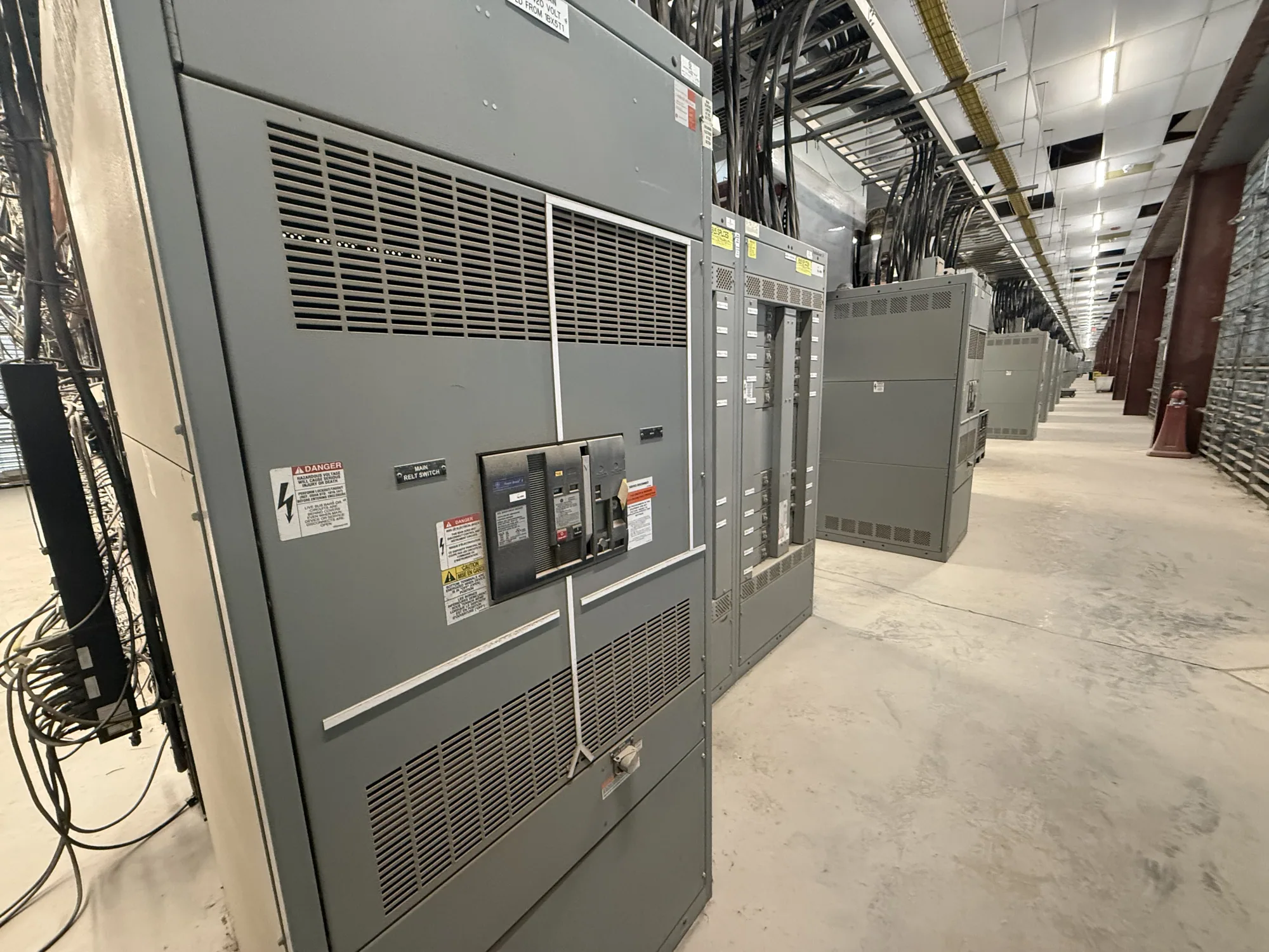
Where low-voltage switchgear fits
Water and wastewater facilities may include pump stations, treatment processes, blowers, controls, and auxiliary systems, each with distinct operating needs. Low-voltage switchgear can distribute power and provide protective devices for loads within the assembly’s specified design. The right arrangement depends on the facility’s electrical system and the equipment it must serve—not simply the industry label or the presence of motors.
For a new installation or replacement scope, first establish which loads belong on the switchgear and which are supplied by other equipment. A project might involve process pumps, ventilation, or control-related distribution, but their actual connection and protection requirements must come from the project design. Remote or outdoor locations add site and enclosure questions; they do not, by themselves, determine a particular assembly configuration.
Define the electrical system before selecting an assembly
Document the nominal system voltage, phase and wire configuration, grounding arrangement, and available fault-current information provided by the responsible engineer. Confirm the equipment’s maximum voltage and insulation requirements against the project specification. Nominal voltage and maximum equipment voltage are related but are not interchangeable, and no single rating should be inferred from a broad description such as “low voltage.”
Interrupting and withstand requirements are also essential selection inputs. The protective devices and assembly must be evaluated for the actual system conditions and specified duties. Ask the project engineer to identify the applicable fault-current basis, required device ratings, and any coordination objectives. These values cannot be established from the facility type alone, and they should not be guessed to accelerate a quotation.
Account for motor loads and operating behavior
Pumps and other motor loads can influence the distribution design, especially where several loads operate together or starting behavior affects the electrical system. Provide motor schedules with available nameplate information, starting method, operating sequence, and any known demand or coordination constraints. The responsible engineer should confirm how these loads affect protective-device selection and the switchgear’s specified ratings.
Consider how the facility is expected to run, not just its connected equipment list. Identify essential processes, standby or alternate sources if included in the design, and the consequences of planned outages or equipment isolation. These details can inform section layout and operating boundaries. They do not establish a guaranteed continuity level; the project team must define the required operating scheme and verify that the selected equipment supports it.
Make maintainability and space part of the design
Ask how operators and qualified maintenance personnel will access devices, inspect the assembly, and work within the facility’s established safety procedures. Available working space, cable entry direction, conduit routes, room access, and equipment movement paths can constrain dimensions and section arrangement. Share room plans and clearances early, including any limits on height, width, depth, or route from delivery point to installation location.
Remote or outdoor applications warrant careful review of the actual environment and specified enclosure conditions. Where moisture, corrosive exposure, washdown, temperature variation, or airborne contaminants are present, describe them precisely and ask the project engineer to define suitable requirements. Do not assume a standard enclosure or finish addresses every site condition. Confirm the proposed design against the project specification before ordering.
Coordinate controls and facility interfaces
Water and wastewater operations often involve control systems alongside power distribution. Identify the interfaces the switchgear must accommodate, such as specified control power, monitoring points, communications provisions, or interlocks. Provide the control drawings or interface schedule when available, and distinguish required functions from possible future provisions. Compatibility and inclusion depend on the actual design and must be confirmed for the quoted assembly.
Map incoming and outgoing connections, cable sizes when established, termination locations, and any transition to adjacent equipment. Include the project’s one-line diagram, equipment schedules, and relevant specifications so the manufacturer can review the intended scope. Also state outage windows, sequencing constraints, and coordination milestones. These are project inputs—not promises of field work, installation, or commissioning by the equipment manufacturer.
Prepare a complete purchase scope
A useful request for quotation identifies the facility application, quantity, nominal voltage and system configuration, required ratings, protective-device scope, enclosure conditions, dimensions, cable entry, and control interfaces. Attach the latest one-line diagram, relevant schedules, and specification sections. Flag unresolved information clearly so the engineer and manufacturer can identify what must be confirmed rather than silently filling gaps with assumptions.
South Carolina Switchgear Builders manufactures new, custom-to-specification low-voltage switchgear, with US-built equipment and all-American components. Availability and actual lead times depend on the order and must be confirmed. Listing, testing, ratings, standards, and configuration are specific to the proposed design; any applicable assembly listing must be verified against that design. Engineering approval, installation, testing, and maintenance remain with the responsible project professionals and qualified personnel. A complete, coordinated scope gives the team a clearer basis for evaluating the equipment and planning the purchase.