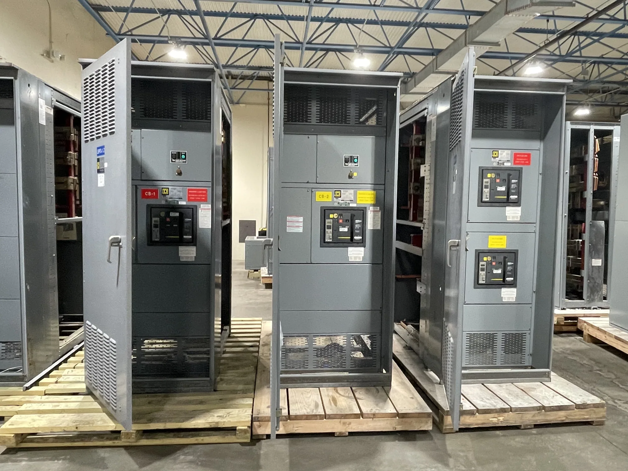
Where medium-voltage distribution fits — Medium-Voltage Switchgear for Aerospace Manufacturing
In an aerospace manufacturing facility, medium-voltage switchgear may receive power from a utility or on-site source and distribute it to transformers or other downstream systems. Those systems can serve precision production equipment, test areas, environmental controls and process support loads. The appropriate arrangement depends on the facility’s one-line diagram, electrical study and operating requirements; the switchgear should be specified as part of that system, not as an isolated purchase.
Consider a facility planning new capacity for a production cell or test operation while keeping other areas in service. The design team needs to understand which loads share a source, which can be interrupted, and how the new feeder will connect to existing distribution. This context shapes lineup configuration, protection interfaces and the work sequence. A manufacturer can supply new equipment to a confirmed specification, while facility engineering and qualified contractors determine system design and field execution.
Match the voltage class and interfaces
Start by confirming the system voltage and the equipment class required by the project. Medium-voltage switchgear is distinct from a 480 V class low-voltage switchboard; the terms are not interchangeable. Provide the nominal system voltage, grounding method, source arrangement and the electrical drawings used for design. Ask the responsible engineer to identify insulation requirements and any environmental conditions that affect the specified construction, rather than assuming a standard configuration will suit the site.
Isolation and switching needs should reflect how the facility expects to operate and maintain its distribution. Identify incoming and feeder functions, tie arrangements, interlocks, metering and control requirements, and any interfaces to facility monitoring. For quality-sensitive production, the goal is not a claim that switchgear itself prevents process variation; it is a coordinated distribution design that supports safe, predictable operation and planned interruption boundaries. Confirm which functions belong in the equipment and which are provided by external systems.
Coordinate protection with sensitive operations
Protective relays and associated instrument-transformer inputs must fit the system study and the required protection scheme. Share available fault-current information, upstream and downstream device data, grounding details, and the intended coordination approach. The project engineer should confirm settings, selective coordination objectives where applicable, and how protective signals interface with plant controls. Do not assume a relay package or default setting will coordinate with existing equipment without review of the actual system.
Map the loads and consequences of interruption before finalizing feeder assignments. Precision machining, test equipment, ventilation, cooling or other process support may have different shutdown tolerances and restart requirements. Ask operations and engineering staff which loads must remain available, which can transfer, and what alarms or status points are needed. These answers can inform the lineup and interface scope, but continuity outcomes depend on the complete electrical system, operating procedures and connected equipment—not switchgear alone.
Resolve continuous-current requirements
Continuous-current selection requires more than adding nameplate loads. Provide expected normal load current by feeder and bus, planned growth, load profiles, operating modes and any credible future additions. The design team should reconcile these values with the source, transformer and downstream equipment ratings. Confirm the continuous-current rating required for each relevant bus and device from the project specification; a single number should not be presumed to apply to every section or operating condition.
Discuss conditions that may affect usable capacity, including ambient temperature, enclosure location, ventilation, elevation or other specified environmental factors. Their effect depends on the actual equipment design and rating basis, so request confirmation against the proposed assembly and installation conditions. Also distinguish continuous-current requirements from short-circuit withstand and interrupting duties: these are separate selection questions that must align with the system study. No rating or performance result should be inferred before those details are reviewed.
Plan phased changes and outages
For an expansion or replacement, provide existing one-line diagrams, lineup dimensions and connection details, available outage windows, access constraints and the intended cutover sequence. Identify circuits that must remain energized during each phase and who will approve isolation boundaries. These details help determine whether a new lineup can be supplied as a standalone section or must coordinate with other equipment. Compatibility with existing gear should be verified from actual drawings and interfaces, not assumed from voltage class alone.
Early coordination can reduce avoidable scope gaps. Confirm responsibility for engineering studies, relay settings, controls integration, foundations, cable terminations, installation, acceptance testing and commissioning. The manufacturer’s equipment scope is not a substitute for field engineering or installation. Any installation, inspection, testing or maintenance must be performed by qualified personnel following applicable safety procedures; no work should be planned on energized equipment.
Prepare a useful purchase specification
For a quotation, assemble the system voltage and grounding information, one-line diagram, required lineup functions, bus and device current ratings, fault-duty requirements, protection and metering interfaces, environmental conditions, and delivery destination. Include applicable project specifications and clearly mark open decisions. State whether the project is new construction, capacity expansion or a phased change, and describe schedule milestones without treating a requested date as a confirmed delivery commitment.
South Carolina Switchgear Builders manufactures new, US-built medium-voltage switchgear with all-American components, custom to specification, and ships nationwide. Availability and lead time depend on the order and require confirmation. Provide the complete technical scope early so the proposed configuration, applicable ratings, listing or testing details, schedule and supply boundaries can be reviewed for the specific project. That gives the facility team a sound basis to compare the equipment scope with its engineering, contractor and operational plans.