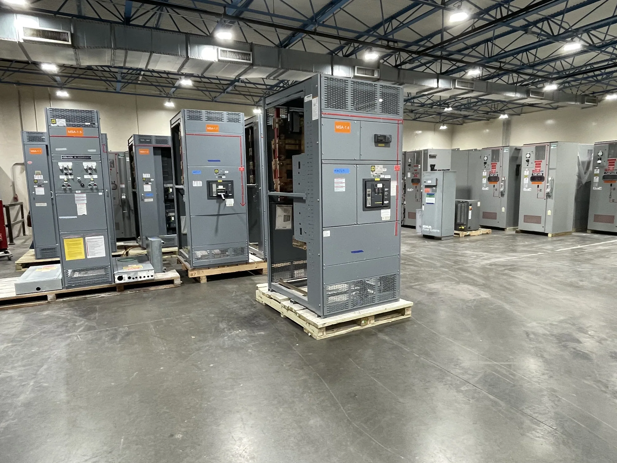
Where medium-voltage switchgear fits in a process facility
In a chemical processing facility, medium-voltage switchgear may receive power from an upstream source and distribute it through feeders to transformers, large motors or other defined loads. The right arrangement depends on the one-line diagram and the role assigned to each bus and feeder; it is not determined by the industry label alone. A project might involve a new process area, a replacement lineup, or a capacity change, each with different interfaces and outage constraints.
Begin by identifying what the equipment must connect, control and protect. Include the source, downstream transformers and loads, normal and alternate operating paths, and any required tie or transfer functions. Confirm whether the requested scope is switchgear, a switchboard, or a combination of assemblies. These terms describe different equipment; a medium-voltage application should be specified for its actual system and design rather than treated as a generic panel package.
Voltage class and system information
State the nominal system voltage and the required equipment maximum voltage as separate project values. They are related but not interchangeable, and the responsible engineer should confirm both against the system and applicable design requirements. Provide frequency, phase and grounding arrangement, available fault-current information, and the source configuration where known. Do not select equipment from nominal voltage alone or assume that equipment in a particular class fits every installation.
Insulation requirements, clearances and switching arrangement also depend on the specified design and site conditions. Ask the project engineer to define applicable insulation levels and any environmental conditions that affect the assembly. Identify altitude, ambient temperature, moisture, dust, corrosive exposure and indoor or outdoor placement where these are relevant. Chemical service can vary substantially from one area to another, so describe actual conditions instead of relying on a broad assumption about all process plants.
Motor feeders, relays and coordination
Large process motors can drive important feeder and protection decisions. Provide motor nameplate and starting information, operating duty, load criticality and the intended starting method, if established. The engineer can use these details to evaluate feeder functions and how starting current, fault protection and process continuity interact. Do not presume a particular breaker, relay feature or setting is appropriate without review of the complete system and motor data.
Define the protective-relay interfaces the lineup must support, including required inputs, outputs, communications or control-power arrangements. Share the protection philosophy, coordination study assumptions and upstream and downstream device information when available. Selectivity and coordination are system-level matters; switchgear alone cannot establish a result. The project engineer must determine the settings and verify coordination using the actual equipment, system data and operating scenarios.
Hazard assessment and equipment placement
Some process areas may be classified because of flammable gas, vapor, dust or other hazards. Provide the facility’s documented area classification and boundaries, along with any applicable site design criteria. Do not assume that ordinary switchgear is suitable for installation within a classified location. Equipment placement should follow the project’s hazard assessment and applicable requirements; the design team may consider locating the lineup outside an unsuitable area and defining safe, approved interfaces to field equipment.
Review access, cable routing, ventilation, working clearances and the route for bringing equipment into the building. Consider whether process shutdowns or limited outage windows constrain tie-ins and commissioning. These conditions affect layout and sequencing, but do not change the need for qualified personnel to install, test and maintain equipment under applicable safety procedures. Confirm the division of responsibility for site engineering and field work before procurement.
Configuration trade-offs and project scope
Bus arrangement, feeder count, metering, protection, control and future provisions should follow the operating philosophy and maintainability goals. A simpler configuration may reduce interfaces, while additional sectionalizing or alternate feeds may support different operating needs and add design complexity. Ask the engineer to compare the actual operating cases, failure modes and outage consequences before fixing the scope. Avoid requesting features by habit if their function and interface have not been established.
Clarify the boundary between manufacturer-supplied equipment and other project work. Specify whether the requested package includes particular protective devices, relays, metering, control wiring, documentation or other components, and identify exclusions. Engineering studies, site installation, system integration and field services should be assigned explicitly to the responsible parties. Listing, testing, ratings and standards are design-specific and should be confirmed for the offered assembly against the final specification.
Prepare a useful equipment inquiry
A focused inquiry includes the one-line diagram, nominal voltage and equipment maximum voltage, system grounding, source and tie details, feeder schedule, motor data, fault-current basis and protection requirements. Add the area classification and equipment location, environmental conditions, cable entry preferences, physical constraints, project schedule and required submittal information. Mark unknowns rather than guessing; the manufacturer and project engineer can identify which open points must be resolved to establish a suitable configuration.
South Carolina Switchgear Builders manufactures new switchgear and switchboards to specification, with US-built equipment and all-American components. Nationwide shipping is available, while configuration, availability and actual lead times depend on the order and must be confirmed. Submit the project requirements for review and quotation, keeping engineering approvals, installation planning and site safety coordination with the qualified project team. A well-defined scope makes the equipment decision more useful and supports orderly coordination from design through delivery.