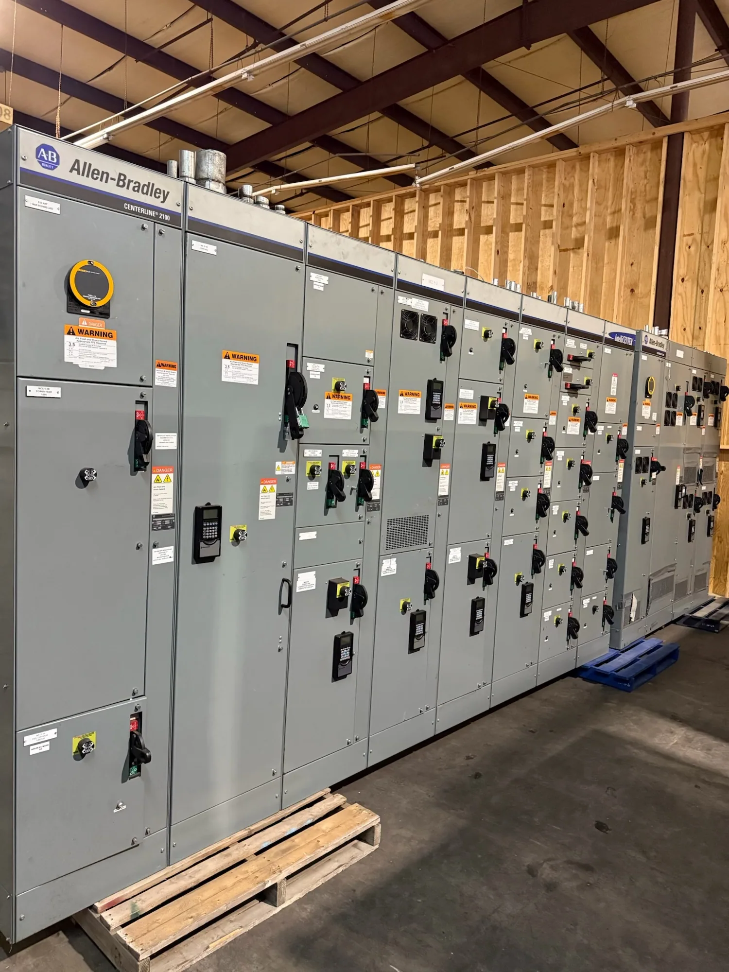
Define the service entrance in the healthcare power plan
For a hospital or healthcare facility, service-entrance switchgear is a central part of the utility-to-building power interface. Its role and boundaries depend on the one-line diagram, service arrangement, and project specifications. The equipment may connect the incoming utility supply with main distribution, while other equipment serves essential electrical systems and alternate sources. Establishing these boundaries early helps keep the switchgear scope aligned with the full electrical design.
Clinical operations make continuity planning especially important, but the main service equipment alone does not guarantee uninterrupted power. The project team must define which loads are essential, how alternate sources connect, what transfers occur, and which distribution paths serve each load. The responsible engineer should coordinate those decisions with applicable codes, healthcare requirements, utility conditions, and the facility’s operating plan rather than relying on a generic equipment arrangement.
Coordinate utility, disconnect, and grounding interfaces
Before requesting a quotation, document the utility service characteristics and the point where utility responsibilities end and customer equipment begins. Confirm the proposed service voltage and configuration, available fault-current information if provided, metering and service-disconnect requirements, connection details, and any utility review or approval process. These items can influence the switchgear arrangement and ratings; they must be established for the specific project, not assumed from another facility.
Grounding and bonding require the same careful coordination. Identify the intended grounding arrangement, service bonding point, neutral treatment, and interfaces with separately derived systems or alternate sources as applicable. Have the project engineer determine the required configuration and verify it against the electrical design and governing requirements. A manufacturer can build to confirmed specifications, but the project’s engineer, utility, and authority having jurisdiction determine and review the applicable design conditions.
Connect essential systems and alternate sources deliberately
Hospitals may have normal and alternate power sources, but their relationship to service-entrance equipment varies by design. Provide a one-line diagram showing utility service, generators or other sources, transfer equipment, emergency and legally required systems where applicable, and the downstream distribution boundaries. Clarify which components are part of the requested supply and which are furnished by others. This prevents misunderstandings about transfer functions, interconnections, and responsibility for controls.
Selective coordination should be addressed where required by the project, with the responsible engineer establishing the applicable devices, time-current study assumptions, and documentation. Equipment selection alone cannot establish a coordination result. Likewise, continuity and outage planning should account for construction phasing, cutover constraints, temporary arrangements, and the facility’s approved procedures. Installation, testing, maintenance, and any switching work belong to qualified personnel following applicable safety procedures; do not treat energized work as a routine installation option.
Resolve voltage and equipment ratings from the actual design
Specify the nominal system voltage and configuration, then distinguish those values from the equipment’s required maximum voltage and insulation characteristics. A voltage label by itself does not resolve all equipment requirements. The project documents should also identify frequency, phase and wire arrangement, grounding approach, and any other electrical characteristics the engineer determines. For example, 480 V class equipment is low voltage, while 5 kV and 15 kV class equipment are medium voltage; these categories should not be conflated.
Ask the responsible engineer to confirm the required continuous-current, short-circuit, withstand, and other applicable ratings from system studies and utility data. Also establish enclosure, access, cable-entry, environmental, metering, and protective-device requirements where they apply. Ratings, listing, testing, and standards depend on the specific assembly and specification. UL 891 may apply to eligible low-voltage switchboards, but it should not be presumed for every assembly or applied to medium-voltage switchgear; verify applicability and listing for the actual design.
Build a complete healthcare project RFQ
A useful request for quotation includes the one-line diagram, equipment scope, voltage and configuration, utility interface details, available fault-current information, requested ratings, and specified protective devices. Add drawings or schedules showing feeder quantities, cable or bus connections, metering, controls, enclosure and access constraints, and any required compartments or barriers. State whether the request covers service-entrance equipment only or includes related distribution equipment, and identify items furnished by others.
Include the project location, delivery constraints, required submittal information, review milestones, and the date equipment is needed on site. Share known outage windows, phasing restrictions, and coordination contacts, while leaving engineering decisions with the responsible professionals. Identify which approvals, inspections, studies, and field work remain outside the manufacturer’s supply. Clear scope information supports a more useful quotation and gives the team a basis for resolving open questions before fabrication.
Coordinate supply, review, and delivery
South Carolina Switchgear Builders manufactures new switchgear and switchboards in the United States, using all-American components, and can configure equipment to a confirmed project specification. Nationwide shipping is available. Actual availability and lead time depend on the order and must be confirmed; do not plan a hospital cutover around an unverified delivery assumption. Review the proposed scope, drawings, ratings, and interfaces with the project team before approving the equipment for production.
For a sound next step, send the current electrical documents and identify unresolved utility, engineering, and facility decisions. The manufacturer can clarify what information is needed to quote the specified equipment, while the project engineer and other responsible parties confirm design, approvals, installation, and commissioning responsibilities. This division of work keeps purchasing focused on the correct new equipment and helps the hospital team coordinate the equipment package with its broader power-continuity plan.