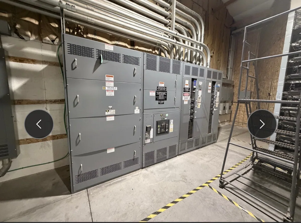
Where service-entrance equipment fits — Service-Entrance Switchgear for Food and Beverage Facilities
In a food or beverage facility, service-entrance switchgear is the main distribution point between the incoming electrical service and downstream plant systems. It may serve refrigeration, process motors, packaging lines, lighting, and building loads, but the actual arrangement depends on the utility connection and the facility’s electrical design. Treat the equipment as one part of a coordinated distribution system, not as a substitute for motor-control or process equipment.
For a project with washdown zones, sanitation procedures, or temperature-controlled areas, start by mapping the equipment location and its surroundings. Record where water, cleaning chemicals, condensation, heat, dust, or corrosive agents could reach the gear. These conditions can influence enclosure selection, access, ventilation, and placement. The project engineer should establish environmental requirements and confirm that the proposed design is suitable for the actual installation.
Coordinate the utility interface and service disconnect
Before defining an equipment lineup, gather the serving utility’s service information and the engineer’s one-line diagram. Confirm the service voltage and phase, available fault-current information, metering arrangement, service disconnect requirements, grounding and bonding approach, and any utility or authority review criteria. These details affect the incoming section, protective devices, metering provisions, and physical layout. Requirements are project-specific; do not assume a typical utility arrangement applies to another site.
Discuss the boundary between utility work, customer-owned equipment, and downstream distribution early. Clarify who supplies service conductors, meter provisions, protective devices, and connections, as well as who obtains approvals and coordinates inspections. The manufacturer can build equipment to an agreed specification, but the responsible electrical engineer and project team must resolve system design, code interpretation, and utility acceptance. Provide documented requirements rather than relying on a general description of the facility.
Account for process loads and continuity needs
Refrigeration compressors, pumps, conveyors, and packaging machinery can create different operating and starting demands. Ask the engineer to identify which loads operate simultaneously, which start frequently, and which processes cannot tolerate an interruption. This information helps define feeder arrangements and protection coordination with downstream motor-control equipment. Service-entrance switchgear distributes and protects circuits according to its design; it does not, by itself, provide process sequencing or keep loads running during a supply outage.
Continuity planning should reflect the consequences of losing refrigeration, production, or sanitation-support loads. The project team can evaluate whether separate feeders, selective protective-device coordination, alternate sources, or other measures belong in the broader system. Each choice affects equipment arrangement, protection, space, and cost. Confirm the required operating sequence and outage constraints with facility operations and the engineer before releasing a design, especially where construction or replacement must fit a planned shutdown.
Specify current ratings from real operating conditions
Do not select continuous-current ratings from connected load totals alone. Provide the calculated demand, expected operating profile, load growth assumptions, ambient temperature, enclosure location, ventilation conditions, and any other factors the design engineer identifies. The engineer should determine the required bus and device ratings and assess applicable derating conditions. A rating must be evaluated for the actual assembly and installation, rather than inferred from a generic application description.
Ask how the specified bus rating, main-device rating, and feeder-device ratings relate to one another and to the system’s load calculations. Confirm the required short-circuit and protective-device information from the project documents, without assuming an unverified value. If future production expansion is anticipated, describe the expected additions and timing so that available spaces or capacity can be evaluated as part of the design. The manufacturer can review these requirements against the proposed equipment specification.
Manage washdown exposure and sanitation interfaces
Electrical gear is not process equipment, and its location should be considered in relation to sanitation routes, hose reach, chemical use, and maintenance access. Share facility plans showing nearby drains, doors, process lines, washdown boundaries, and equipment-clearance constraints. The design team should determine whether the proposed location and enclosure provisions address the documented exposure. Do not assume that a standard enclosure is suitable for direct washdown or any particular cleaning chemical.
Plan for safe access without obstructing egress, production circulation, or required working clearances. Consider how technicians will inspect and service the lineup under the facility’s safety procedures, and how planned outages can be coordinated with operations. Installation, testing, and maintenance are tasks for qualified personnel following applicable safety procedures. Any environmental protection, labeling, or special construction should be stated in the purchase specification and confirmed for the particular design.
Prepare a complete equipment request
A useful request package includes the one-line diagram, service data, load calculations, required ratings, protective-device preferences, metering needs, enclosure and environmental requirements, available floor space, cable-entry direction, and connection details. Add drawings or notes identifying refrigeration and process loads, sanitation exposure, planned expansion, and shutdown windows. State the project location and requested delivery schedule so availability and timing can be reviewed for the specific order.
South Carolina Switchgear Builders manufactures new switchgear and switchboards to specification, with US-built equipment, all-American components, and nationwide shipping. Actual configuration, availability, delivery dates, ratings, testing, and any listing applicability require confirmation against the project specification and supplied assembly. Where a low-voltage switchboard is proposed, verify whether UL 891 applies to that specific eligible design; do not assume it applies to all equipment. Define engineering, installation, field testing, and utility coordination responsibilities separately from the manufacturer’s equipment scope.
Move from facility requirements to a reviewed specification
Before ordering, have the project engineer reconcile utility requirements, load calculations, grounding and bonding, environmental conditions, clearances, and protection details. Operations staff can validate process priorities and acceptable outage windows, while the purchasing team confirms scope boundaries, documentation needs, and schedule expectations. This review helps identify missing information before fabrication and gives the manufacturer a clear basis for evaluating the requested configuration.
When requesting a proposal, distinguish mandatory requirements from preferences and flag any unresolved utility or site questions. Confirm all ratings, construction details, approval expectations, and delivery timing in the project documents before authorization. A well-defined equipment scope supports a more useful review of the service entrance and its role in the facility’s distribution plan, while leaving system design and field work with the qualified professionals responsible for them.