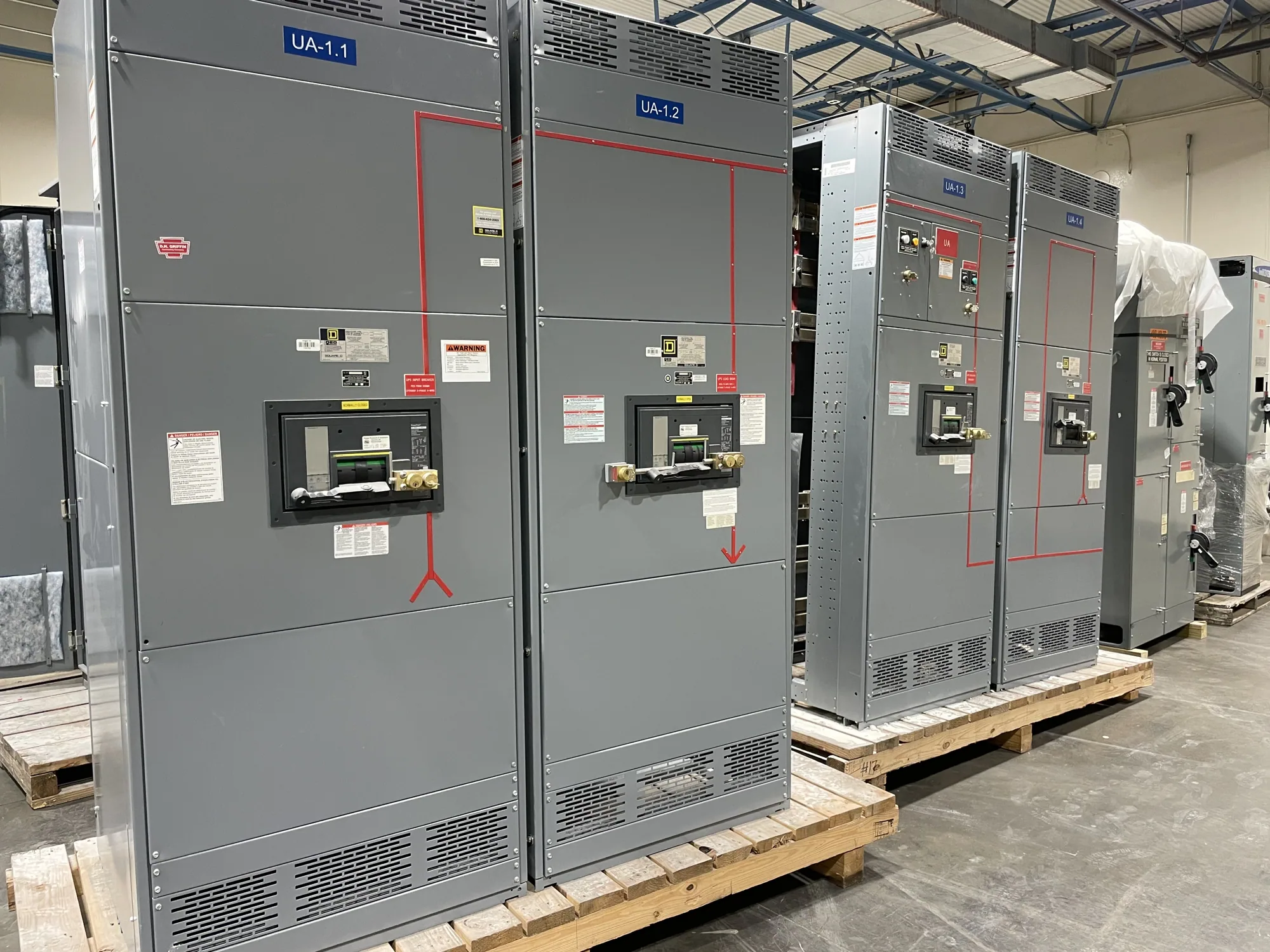
Where medium-voltage switchgear fits — Medium-Voltage Switchgear for Food and Beverage Facilities
In a food or beverage facility, medium-voltage switchgear can receive and distribute power to transformers, major process areas, refrigeration systems, and other loads defined by the electrical design. It is not a substitute for low-voltage motor control centers or local disconnects; rather, it supports the upstream distribution architecture. The right arrangement depends on the facility’s service, voltage class, operating plan, and division of equipment between electrical rooms and production spaces.
Consider a hypothetical plant with large refrigeration compressors, process motors, packaging lines, and sanitation activity. These loads may have different operating schedules and consequences when interrupted. The project engineer should identify which feeders serve each area, how transformers and downstream distribution are arranged, and which loads require coordinated restart or backup plans. This information helps determine switchgear lineup functions and interfaces without assuming a single configuration suits every facility.
Match the design to the environment
Begin by confirming the system voltage and equipment location. A 5 kV or 15 kV class application is medium voltage; the project documents should establish the actual system and equipment requirements. Specify the electrical-room conditions, including expected ambient temperature, humidity, dust, corrosive exposure, and ventilation. Washdown practices matter even when the switchgear is located outside production areas: nearby hose use, cleaning chemicals, doorways, and air movement can affect the room environment and installation details.
Discuss enclosure construction, insulation system, access, and maintenance clearances with the responsible engineer and manufacturer. The switchgear should be specified for its intended indoor or outdoor location and the conditions documented for that location. Sanitation procedures should not be assumed compatible with electrical equipment. Keep the equipment outside direct washdown zones unless the project design explicitly addresses exposure, and coordinate room boundaries, drains, penetrations, and cleaning practices with facility and sanitation teams.
Coordinate motor loads and protection
Large motors can influence feeder selection, switching duties, and protective-device coordination. Provide motor data such as rated voltage, horsepower or kilowatt rating, full-load current, starting method, starting frequency, and any required operating sequence. Identify whether motors start across the line or through downstream equipment, and whether simultaneous starts are expected. The engineer can use these details to assess the system and specify suitable switchgear interfaces; do not assume every motor feeder requires the same device or control arrangement.
Protection requirements should reflect the system study and operating philosophy. Clarify relay functions, instrument-transformer requirements, trip and close circuits, control power, alarms, communications, and signals exchanged with plant controls or supervisory systems. If refrigeration or process continuity is important, describe acceptable interruption, transfer or restart expectations, and the consequences of losing individual feeders. Switchgear supply does not by itself establish a complete protection study, plant control scheme, or continuity plan.
Understand continuous-current requirements
Continuous current is a system-design question, not a number to select from a general application description. The engineer should calculate expected normal load current from the equipment schedule and operating assumptions, then specify bus and device ratings appropriate to the system and applicable design conditions. Provide present loads, planned expansions, diversity assumptions, motor duty, and any known periods of sustained peak operation. Explain which loads can run concurrently rather than relying only on connected-load totals.
Ask how ambient temperature, enclosure conditions, ventilation, conductor arrangement, and the selected equipment configuration affect the specified ratings. The assembly and individual devices must be evaluated against the actual application; a nameplate value alone does not resolve installation-specific conditions. Confirm the required continuous-current rating, short-circuit duty, and other system parameters with the project engineer and manufacturer before ordering. No rating or derating conclusion should be assumed without the completed specification.
Plan isolation and operational access
Production schedules can make outages difficult to coordinate. Identify maintenance windows, seasonal peaks, sanitation shutdowns, and dependencies between refrigeration, process, and packaging operations. The engineer should define isolation points and switching sequences, and determine whether the distribution arrangement supports the required operating plan. Where separate sources or alternate feeds are contemplated, document the intended normal configuration and transfer conditions for review rather than presuming a particular lineup or automatic scheme.
Also plan the physical interfaces early: room dimensions, cable entry and routing, grounding, control wiring, equipment access, and the route from receiving to final location. Confirm who is responsible for foundations, terminations, protection settings, field testing, and commissioning. These tasks may involve the owner’s engineer, electrical contractor, and qualified field personnel; they should not be inferred as included with equipment manufacture.
Prepare a useful equipment inquiry
For a focused quotation, provide the one-line diagram, system voltage, available fault-current information, load and motor schedules, intended lineup arrangement, indoor or outdoor location, and environmental conditions. Include relay and control requirements, communication interfaces, cable entry preferences, space constraints, project schedule, and applicable project specifications. Flag expansion plans, operating priorities, and outage limitations. If documents are preliminary, identify what remains open so assumptions can be reviewed before a final design is established.
South Carolina Switchgear Builders manufactures new medium-voltage switchgear to specification, with US-built equipment and all-American components. Availability and actual lead times depend on the order and must be confirmed; nationwide shipping is available. The manufacturer’s scope should be distinguished from engineering studies, installation, field wiring, testing, and commissioning. Review the proposed equipment details against the project documents, resolve exceptions before release, and coordinate delivery and site readiness with the project team. A clear, complete specification is the practical starting point for equipment that fits the facility’s electrical and operating needs.