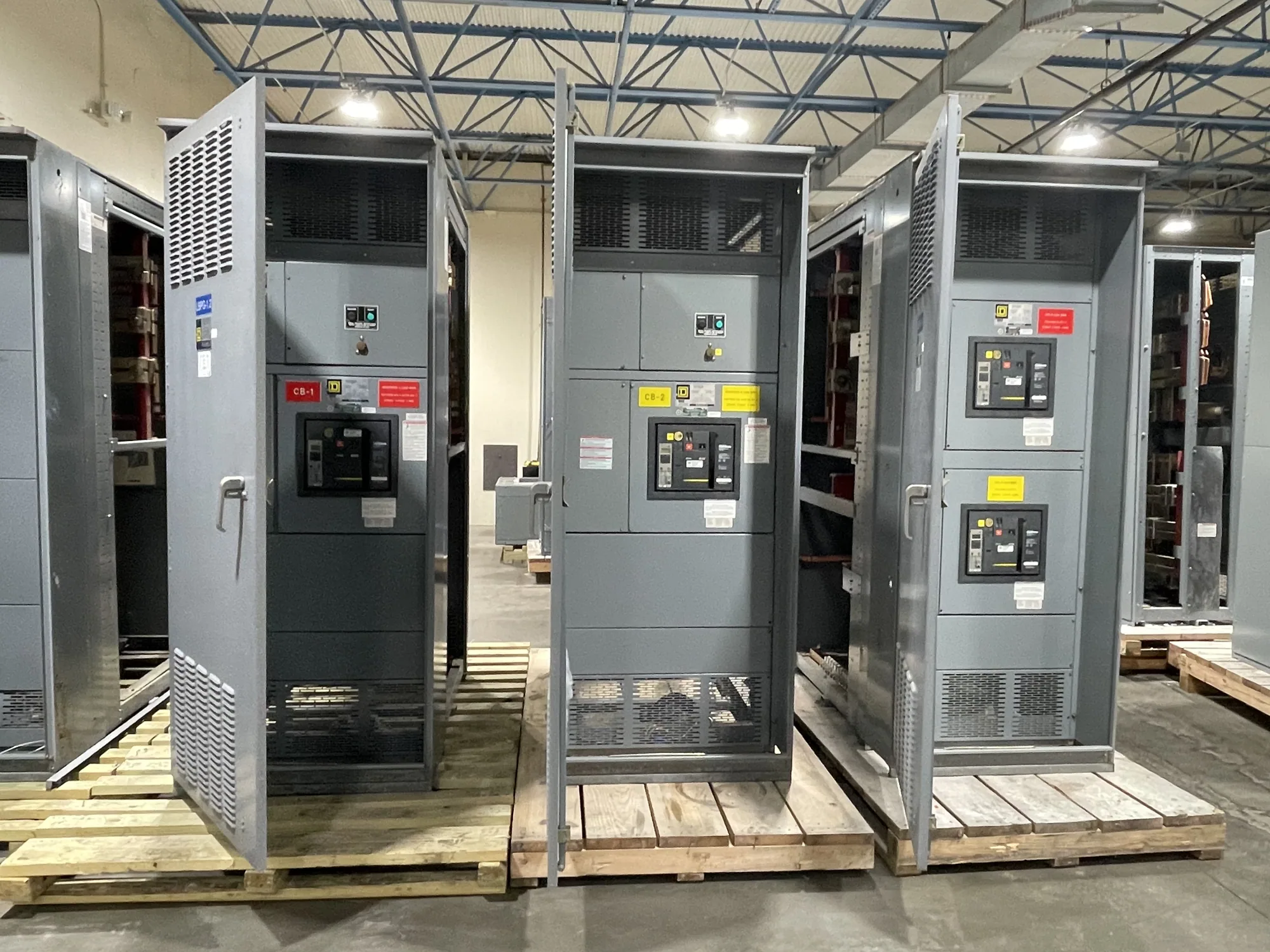
Where metal-clad switchgear fits — Metal-Clad Switchgear for Water and Wastewater Facilities
A water or wastewater project may bring together raw-water pumps, treatment processes, lift stations, plant utilities, and supervisory controls. When a facility’s distribution design calls for medium-voltage equipment, metal-clad switchgear may serve as a coordinated assembly for switching and protecting specified circuits. Its role depends on the one-line diagram, system configuration, and project requirements; it is not automatically the right choice for every pump or facility.
Start by identifying which loads and feeders the proposed lineup must serve. A central treatment plant with several medium-voltage motors presents different coordination questions from a remote pumping site or an expansion tied into existing distribution. Clarify whether the purchase covers a complete lineup, an addition, or equipment for a defined section of the system. The responsible project engineer should establish how the new assembly interfaces with existing equipment.
Translate pumping loads into equipment requirements
Motor loads deserve particular attention. Provide motor voltage, horsepower, starting method, operating duty, and any known starting or acceleration constraints for each relevant load. The project engineer can use this information to evaluate switching and protection requirements and how motor starting may affect the distribution system. Do not assume a switchgear configuration is suitable based only on motor size or a general description of the treatment process.
Also identify the incoming source, feeder arrangement, expected operating sequence, and whether loads may run simultaneously or transfer between sources. Include the protective-device and control interfaces required by the project, such as signals to plant controls or remote monitoring. Define which devices and wiring are within the manufacturer’s supply and which belong to other project packages. That division helps avoid gaps between switchgear, motor controls, and facility automation.
Resolve voltage and system configuration
Specify the nominal system voltage and ask the project engineer to confirm the required equipment maximum voltage, insulation level, and applicable design requirements. These values are related but not interchangeable. The selected equipment must match the actual system and project specification; do not infer a rating from the facility type, motor description, or a previous installation. Provide available system information and identify any constraints imposed by existing gear.
Describe the system configuration, including source and bus arrangement, grounding approach, feeder count, and any required metering or protection functions. If the design involves an existing lineup, supply drawings and interface details where available. These inputs help determine whether the proposed metal-clad arrangement can be coordinated with the installation. Ratings, protection features, testing, and standards applicability must be confirmed for the specific assembly rather than assumed from a general product category.
Consider compartments, access, and maintenance interfaces
Metal-clad construction uses separated compartments, while removable devices may support defined isolation and maintenance procedures when included in the design. Confirm which circuit breakers or other devices are required, what positions and interlocks are specified, and how operators are expected to access the lineup. The responsible engineer should coordinate those features with the plant’s operating procedures, maintenance plan, and outage constraints.
Discuss practical access early: room dimensions, aisle and door clearances, equipment entry route, cable approach, and the space needed for installation and future service. For a remote or outdoor location, establish whether the project calls for indoor equipment in a building or a separately specified outdoor arrangement. Do not presume that a standard indoor metal-clad lineup is suitable for weather exposure. Enclosure, environmental protection, and installation conditions require project-specific confirmation.
Address corrosion and control integration
Water and wastewater sites can have moisture or corrosive exposure, but conditions vary substantially by process area and location. Describe the actual environment, including whether equipment will be near chemicals, washdown, salt exposure, or persistent condensation. Ask the project team to define suitable materials, finishes, enclosure details, and environmental provisions for that location. A facility label alone is not enough to establish the needed construction.
List control and communication interfaces explicitly. Identify required status, alarm, trip, and permissive signals; control voltage; terminal or wiring expectations; and any communication protocol specified by the project. Confirm who supplies relays, meters, network components, and field wiring. The switchgear manufacturer can address equipment within the agreed scope, while plant controls integration and field connections need clear ownership among the project’s responsible parties.
Prepare a useful purchase scope
For a quote, assemble the one-line diagram, equipment location and environment, voltage information, feeder and motor schedule, desired lineup arrangement, protection and metering requirements, control-interface list, and relevant existing-equipment drawings. Note the project schedule, delivery destination, access limitations, and requested documentation. Identify unresolved engineering questions instead of filling gaps with assumptions; those questions can be reviewed before a configuration is finalized.
South Carolina Switchgear Builders manufactures new switchgear and supplies equipment custom to specification, with nationwide shipping. Actual configuration, availability, applicable listing, testing, ratings, and delivery dates depend on the order and must be confirmed against the project requirements. Manufacturer supply is distinct from system engineering, installation, commissioning, and field maintenance. Qualified personnel should perform installation and testing under applicable safety procedures. A complete scope and clear division of responsibilities give the project team a sound basis to evaluate the proposed equipment for its facility.