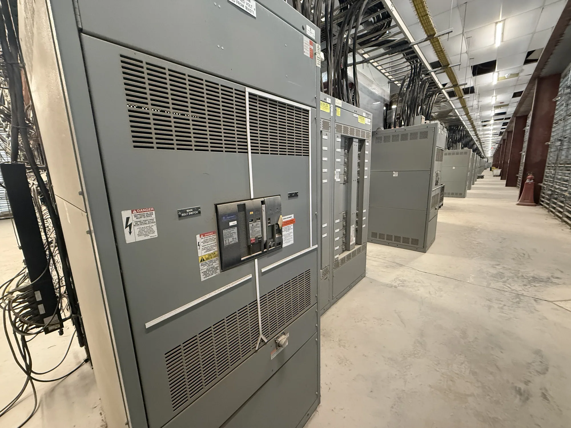
Where metal-enclosed switchgear fits on campus
A higher education campus may distribute power across academic buildings, research laboratories, residence halls, and central plants, each with different operating priorities. In a hypothetical expansion, new metal-enclosed switchgear could serve a building or distribution point connected to several feeders. Its role and construction depend on the specified equipment class and project design; the enclosure alone does not establish voltage, interruption capability, or application suitability.
For a campus project, begin by identifying what the equipment must connect, control, and protect within the planned distribution arrangement. A phased construction program may need new feeders now while preserving defined pathways for future work. The project engineer and owner should establish which loads, sources, and interfaces belong in the equipment scope, and which remain part of upstream or downstream systems.
Choose construction around the actual application
“Metal-enclosed switchgear” is not a complete construction specification. The required arrangement, switching devices, barriers, compartments, and access provisions depend on the equipment class and project requirements. Provide the applicable voltage class and system details, and ask the responsible engineer to identify the construction and functions needed. Do not assume that a particular enclosure arrangement, device type, or feature is appropriate solely because the project serves a campus.
Consider how maintenance and operating access will work in the intended room or outdoor location. Share room dimensions, door and equipment access routes, adjacent services, cable entry expectations, and any planned working clearances established by the project team. For central plants and laboratory buildings, coordinate equipment interfaces with the facility design and owner standards. The manufacturer can configure new equipment to an approved specification; site layout and installation planning remain project responsibilities.
Coordinate feeders, grounding, and switching
Multi-building feeder planning calls for a clear one-line diagram and an agreed definition of each circuit. Identify feeder destinations, source connections, normal operating arrangements, switching functions, and any intended spare provisions. Where construction is phased, explain which parts are included in the current order and what future interfaces must be accommodated. The engineer should confirm protection and coordination requirements rather than leaving them to be inferred from a general equipment description.
Grounding requirements also need project-specific definition. Provide the system grounding approach and any grounding or bonding interfaces shown in the design documents, then confirm how they apply to the requested assembly. Clarify device operation, interlocks, and access expectations where they affect campus procedures. Scheduled outage windows may constrain when existing connections can be changed, but they do not establish that installation or commissioning can be completed within a particular interval; coordinate that work with the responsible contractors and owner.
Resolve continuous-current ratings with project data
Continuous-current ratings should be selected from the project’s electrical requirements, not from a campus-wide assumption. Provide expected normal load current for each relevant bus and feeder, the system configuration, and the specified current ratings for switching and protective devices. Ask the project engineer to verify that the proposed bus and device ratings suit the intended operating conditions and design basis.
Operating environment can affect the final selection. Share available information about equipment location, ambient conditions, enclosure arrangement, loading patterns, and any project-defined temperature or ventilation constraints. Ask whether derating or other adjustments apply to the specific design and supplied equipment. A manufacturer should confirm the offered configuration against the complete specification; do not treat a nominal current value as proof that every device, bus section, or operating condition is suitable.
Build a complete purchasing specification
A useful request for quotation includes the one-line diagram, equipment class and voltage, system grounding details, feeder schedule, required switching functions, and specified bus and device current ratings. Add applicable owner standards, drawings, preferred construction details, room or site constraints, cable interface information, and the requested delivery destination. Identify the project phase and distinguish firm requirements from items still awaiting engineering confirmation.
Also state the required submittal information and any project-specific expectations for ratings, testing, listing, or standards. Applicability depends on the actual design and supplied equipment, so request confirmation rather than assuming a general product description establishes compliance. If the project has a planned outage or construction milestone, communicate the dates as coordination needs, not as an assumed delivery or completion guarantee.
Coordinate supply with campus project responsibilities
South Carolina Switchgear Builders manufactures new switchgear and switchboards in the United States, using all-American components, and ships nationwide. Equipment can be custom to specification, and short lead times may be available; actual availability and delivery timing depend on the order and must be confirmed. A complete, coordinated specification helps clarify what is being quoted and where design decisions still require the project team’s direction.
Manufacturer supply is distinct from system engineering, site preparation, installation, field testing, and outage execution. Confirm who owns each activity, who approves submittals, and how questions will be resolved before equipment is released for production. Installation, testing, and maintenance should be performed by qualified personnel under applicable safety procedures. With campus loads, interfaces, ratings, and project boundaries clearly documented, the buyer can evaluate a proposed assembly against the real requirements instead of relying on assumptions.