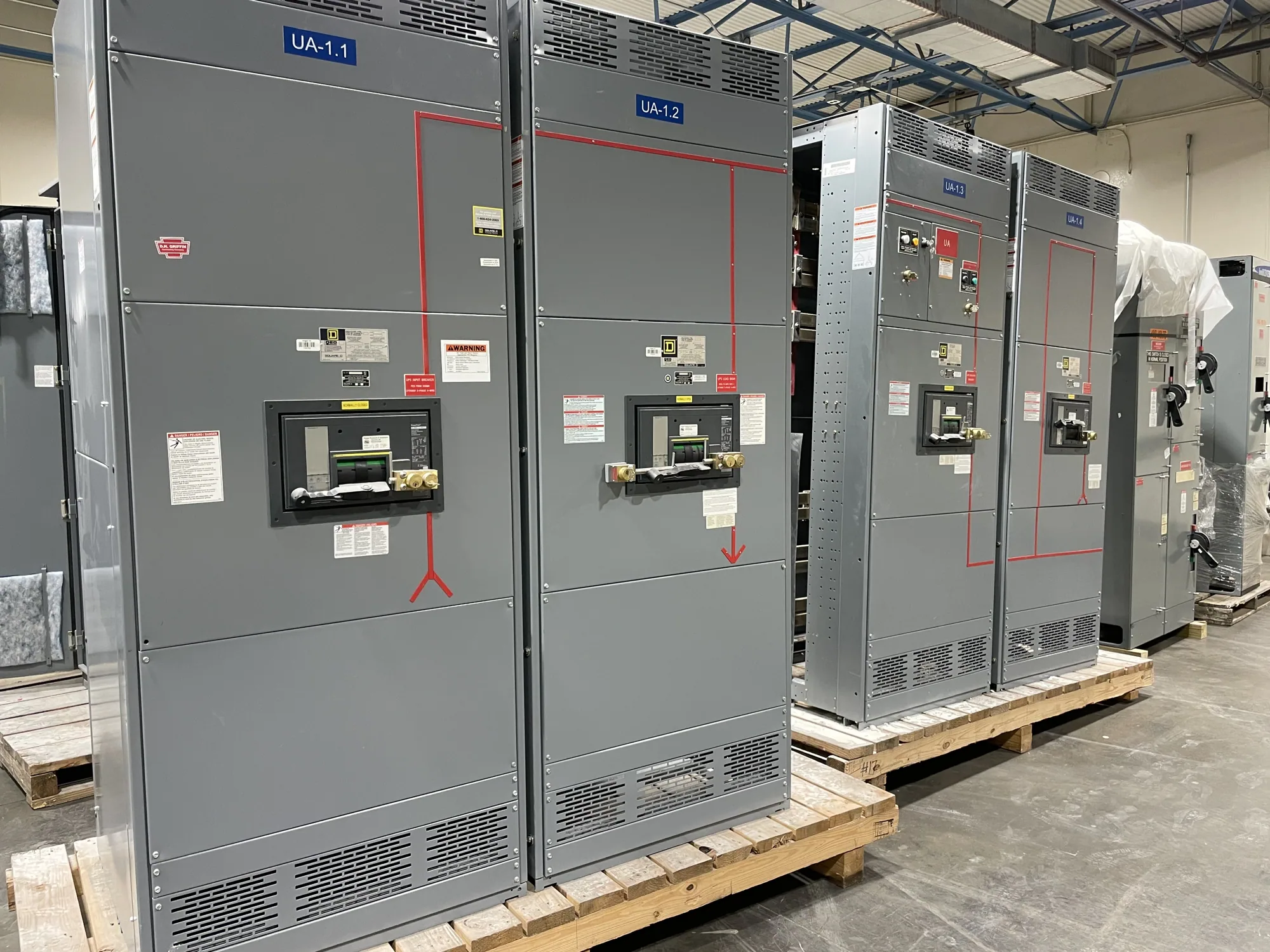
Where an MCC fits in a process facility
A motor control center (MCC) groups motor-control units and associated distribution equipment in a coordinated assembly. In a chemical processing facility, it may serve pumps, agitators, compressors, fans, conveyors, or other motor-driven process equipment. The required arrangement depends on the electrical design and operating needs; an MCC is not simply another name for switchgear, and it does not replace the facility’s complete distribution and protection plan.
For a project considering a new MCC, begin with the loads and the process areas they serve. Identify which motors need across-the-line starters, reduced-voltage starting, or variable-frequency drives, and note which loads are critical to safe shutdown or continuity. The responsible project engineer should establish the electrical architecture and determine where an MCC is appropriate. Manufacturer scope should then be defined against those approved project requirements.
Hazard assessment and equipment location
Chemical facilities can include areas with different environmental conditions and classifications. Do not assume an MCC can be installed in a potentially classified area because a particular enclosure or unit appears suitable. The project’s qualified professionals must determine the area classification, applicable equipment requirements, and acceptable location. Equipment may need to be placed outside an unsuitable area, with motor circuits routed to process loads as the engineered design allows.
Also describe the actual installation environment: ambient conditions, dust or corrosive exposure, moisture, washdown practices, ventilation, and available floor space. Those conditions can affect enclosure selection, layout, heat management, access, and maintenance planning. Identify nearby equipment and building constraints, too. A manufacturer can evaluate the requested configuration, but the owner’s engineering team must confirm that the proposed equipment and location meet project and site requirements.
Motor units, drives, and heat
Prepare a motor schedule with each load’s name, quantity, voltage, horsepower or other specified motor data, starting method, and operating duty. Include spare or future units as clearly identified allowances rather than treating empty spaces as a guaranteed future fit. For drives, provide the required drive data and explain which motors need speed control, bypass, or specific control interfaces. Confirm the intended arrangement with the engineer and manufacturer before the design is finalized.
Starters, drives, and other devices generate heat, while process conditions may limit ventilation or access. Ask how the proposed lineup’s internal heat and installation environment will be addressed, and provide the available room conditions and any enclosure constraints. Unit density, continuous operation, drive selection, and ambient conditions can influence the practical arrangement. The final design should be reviewed against the project specification rather than assumed from a generic MCC layout.
Voltage and protection coordination
State the nominal system voltage and configuration, including the information needed to distinguish the system’s grounding and phase arrangement. Also identify any specified equipment maximum voltage and insulation requirements. These are related but not interchangeable values; do not select an MCC from a nominal voltage label alone. The responsible engineer should establish the applicable system details, and the manufacturer should confirm that the requested equipment configuration matches the specification.
Protection must be considered in the context of the complete electrical system. Provide available fault-current information when established, upstream protective-device details, motor protection requirements, and any project coordination criteria. The engineer responsible for the system should determine settings, coordination objectives, and device application. A manufacturer’s equipment proposal does not replace a project-specific coordination study or establish performance results that have not been verified for the actual design.
Interfaces, outages, and operations
List control and communications interfaces, including required signals, interlocks, network protocols, and connections to process control systems. Identify who supplies field devices, cables, programming, and interface engineering. Define how alarms, permissives, emergency shutdown functions, and local controls are expected to interact, then assign responsibility for confirming those details. Clear boundaries reduce late changes between the MCC, process controls, and facility distribution work.
For replacement or expansion projects, document the existing system, physical access, cable entry, connection points, and outage windows. State what must remain in service and which loads can be interrupted, without assuming a particular tie-in approach. The owner and project team should plan sequencing, installation, testing, and commissioning with qualified personnel under applicable safety procedures. Manufacturer supply should be distinguished from field installation, engineering, and commissioning unless those services are specifically included and confirmed.
Information for a useful equipment proposal
Send the single-line diagram, load and motor schedules, written equipment specification, voltage and system data, area-classification documentation, environmental conditions, control requirements, and requested lineup dimensions or restrictions. Include applicable project standards and identify any required listing or testing expectations for confirmation against the particular assembly. Note spare-unit plans, critical loads, delivery destination, and target project milestones; availability and actual lead times depend on the order and must be confirmed.
South Carolina Switchgear Builders manufactures new equipment to specification, with US-built construction and all-American components, and ships nationwide. Share the project documents and open technical questions so the requested MCC scope can be reviewed against the facility’s motor loads, location constraints, and electrical requirements. Confirm configuration, ratings, applicable standards, availability, and delivery dates for the specific order before procurement and coordinate the equipment boundary with the project’s engineering and installation teams.