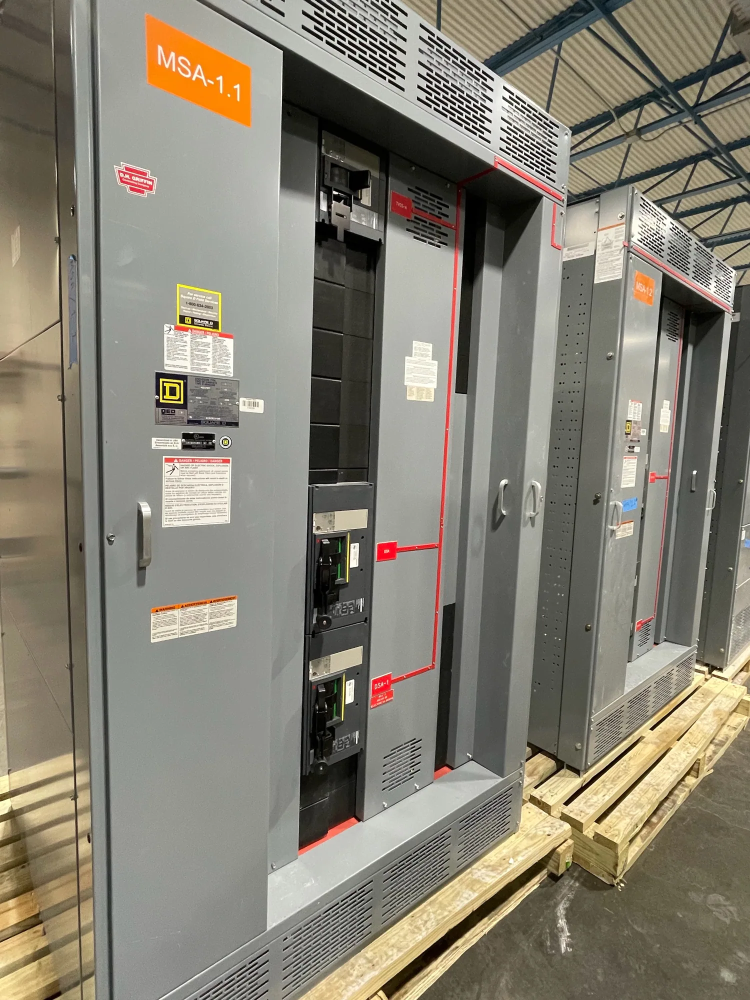
Where a motor control center fits in healthcare power
A motor control center (MCC) groups motor-control units, such as starters and, when specified, drive units, in a common assembly. In a hospital or other healthcare facility, it may serve designated motors for equipment such as pumps, fans, or other building systems. The MCC is not a substitute for the facility’s service switchgear, switchboard, emergency power system, or essential electrical system. Its role and boundaries need to be clear on the one-line diagram and equipment schedule.
Consider a project with normal and alternate power sources, clinical operations, and loads assigned to different branches of the electrical system. The responsible project engineer determines which motors belong on each source and how the transfer and distribution arrangement works. An MCC’s configuration must match that engineered scheme; the product name alone does not establish that it is suitable for essential-system duty. Identify the loads, source arrangement, required operating sequence, and interfaces before requesting a quotation.
Map motor loads and operating behavior
Build the scope from the motor list rather than a general building description. For each load, provide its function, motor nameplate information, starting method, operating schedule, and any required control or interlock points. Distinguish continuous, intermittent, standby, and staged operation where those categories apply to the project. This helps the design team determine unit types and arrangement without assuming that every motor needs the same starter or operating logic.
Across pumps and fans, direct-on-line starters and variable-frequency drives can involve different starting behavior, controls, and heat dissipation. A drive may support a specified speed-control strategy, while a starter may be appropriate for a motor intended to run at a fixed speed. Those are engineering decisions, not interchangeable product features. Confirm motor compatibility, control intent, bypass needs if any, environmental conditions, and the effect of the selected equipment on the assembly’s thermal design.
Coordinate essential-system requirements and continuity
Healthcare projects may assign loads to normal, emergency, or other defined distribution branches. The project’s electrical engineer should identify the required source, transfer arrangement, and operating sequence for each MCC section or served motor. Confirm whether the assembly is supplied from one source or has a project-defined interface with other equipment. Do not assume an MCC itself performs source transfer or qualifies a load for a particular system category.
Where required by the design, selective coordination must be evaluated across the relevant protective devices and the actual power-system configuration. Provide available fault-current information, protective-device data, upstream and downstream equipment details, and the engineer’s coordination criteria. The manufacturer can configure equipment to the approved specification, but coordination conclusions depend on the complete system and project engineering. Outage windows, temporary operating plans, and work sequencing also belong in the facility’s project planning; installation and field work must be handled by qualified personnel using applicable safety procedures.
Resolve voltage and assembly details
Specify the nominal system voltage and configuration, frequency, grounding arrangement, and the equipment’s required maximum voltage as separate items. They are related but not interchangeable. The responsible engineer should confirm the insulation and other electrical requirements for the actual system, including how the MCC connects to its source and loads. Do not select an assembly from nominal voltage alone or infer an equipment rating from the voltage of another part of the facility.
Also establish bus requirements, enclosure and room conditions, cable-entry preferences, short-circuit and protective-device requirements, unit space, and any requested metering or control interfaces. Temperature, ventilation, altitude, and nearby equipment may affect design choices and need to be stated for review. Future motor capacity should be expressed as a defined allowance or identified spare units, not an assumed promise of unlimited expansion. Verify that the proposed arrangement fits the electrical room and supports planned cable routing and access.
Prepare a useful manufacturer RFQ
A complete request for quotation should include the one-line diagram, MCC schedule, motor list, project specifications, applicable drawings, and required submittal format. State the source and branch assignments, control descriptions, device preferences if established, and known interface points. Flag unresolved items instead of treating them as fixed requirements. Include project location, requested shipment timing, and the parties responsible for engineering approval, installation, commissioning, and field testing.
South Carolina Switchgear Builders manufactures new motor control centers to specification, with US-built equipment and all-American components. Availability and actual lead times depend on the order and must be confirmed. Provide the complete scope early so the manufacturer can identify questions about configuration, components, and schedule before the design is finalized. Confirm applicable ratings, testing, listing, and standards against the specific proposed assembly and project documents; they should not be assumed from a general product description.
Coordinate supply with the healthcare project team
Compare proposals against the same approved requirements: unit arrangement, starter or drive scope, feeder protection, voltage details, interfaces, documentation, and stated exceptions. Ask the engineer to resolve any deviation that could affect the essential-system design, operating sequence, or coordination study. Manufacturer supply is distinct from system design, field installation, programming, commissioning, and maintenance. Assign each task clearly so that assumptions do not carry from a quotation into construction without review.
Before release, align the approved drawings and submittals with room layout, conduit and cable plans, access needs, and the facility’s outage constraints. Confirm the delivery date for the specific order and coordinate receipt and installation with the construction team. A carefully defined MCC scope helps the project team evaluate equipment consistently while preserving responsibility for system design and safe field execution. The result is a purchasing decision grounded in the actual motor loads and healthcare power architecture.