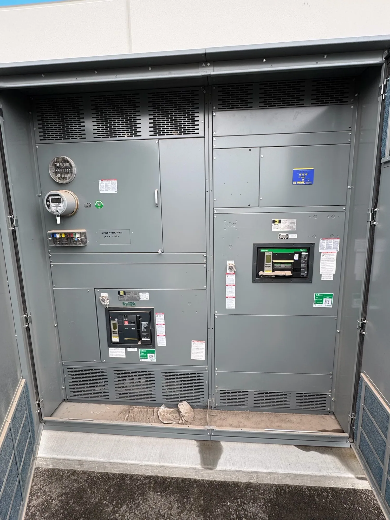
Where an MCC fits in a logistics facility
A warehouse or distribution center may rely on conveyor zones, sortation equipment, dock systems, pumps, fans, and other motor-driven loads. A motor control center (MCC) groups motor branch-circuit components and control equipment in an assembly, with a configuration developed for the project. It is not simply another name for all facility switchgear: the service and upstream distribution arrangement must be defined separately.
For a new facility or expansion, an MCC can provide a planned location for motor starters, drives, and associated feeder protection. The design should follow the actual equipment schedule and operating concept, not an assumed standard warehouse package. Charging equipment, building services, and future automation may affect the broader electrical distribution plan, but they should not be assigned to the MCC without confirming their electrical characteristics and intended connection.
Translate operations into an equipment schedule
Start with a list of loads that identifies each motor, its normal operating current, starting method, duty, and intended control. Include conveyor segments and zones separately where they have distinct motors or operating sequences. Note loads that run continuously, cycle with order volume, or operate only during selected shifts. The project engineer can use this information to coordinate branch-circuit devices and controls with the operating requirements.
Identify which loads may use variable-frequency drives and provide their specifications if selected. Drives can influence enclosure heat, wiring, control interfaces, and coordination with upstream equipment; suitability and configuration depend on the actual design. Also record required interlocks, emergency-stop interfaces, communication protocols, and points of connection to supervisory systems. The manufacturer should receive defined requirements rather than being asked to infer how warehouse controls are intended to work.
Plan feeders, charging assumptions, and growth
Warehouse electrification can make charging demand relevant to the facility distribution plan. Provide the expected charging equipment, operating schedule, charging strategy, and any demand-management assumptions established by the project team. Do not treat a charger as a motor load or assume it belongs in an MCC. Its connection point and effect on feeders, service capacity, and load calculations require review by the responsible electrical engineer.
For planned growth, distinguish equipment included in the initial purchase from loads reserved for a later phase. Specify which future motors or control functions are anticipated, and ask the engineer to assess the implications for bus capacity, feeder protection, physical space, heat, and available connections. Empty or reserved spaces alone do not establish that a future addition will be suitable. Any staged expansion must be planned around the assembly design, approved scope, and facility outage constraints.
Understand current ratings and thermal conditions
Continuous current rating is one part of selection, not a substitute for a complete load review. The project team should provide expected normal current by motor and feeder, operating patterns, simultaneous-load assumptions, and the proposed bus and device ratings. Confirm how the selected assembly is intended to carry the calculated load continuously, and ask the responsible engineer to resolve applicable design conditions before the configuration is finalized.
Operating temperature and enclosure conditions matter, especially where drives or closely grouped equipment contribute heat. Provide the planned installation environment, enclosure location, ventilation constraints, and any known temperature or dust exposure requirements. Derating or other design adjustments may depend on the specific equipment, arrangement, and environmental conditions. The manufacturer can evaluate the configuration against supplied requirements, but the project should not rely on an assumed rating or generic warehouse conditions.
Coordinate protection, interfaces, and installation
Protection and control should be coordinated with upstream devices, motor characteristics, and the facility’s operating needs. Share available system information and the project engineer’s protection and coordination requirements; do not assume a device selection or setting from motor horsepower alone. Confirm control voltage, control-power approach, field wiring boundaries, communications, and responsibility for programming or integration before purchase, so gaps between the MCC and other systems are visible early.
Document room access, delivery route, equipment arrangement, cable-entry preferences, and the installation sequence. If an existing facility must remain operational, identify outage windows and the boundaries of each phase. These details can affect shipping configuration and field assembly planning. Installation, inspection, testing, and maintenance are the responsibility of qualified personnel following applicable project requirements and safety procedures; supplying the assembly does not itself provide those field services.
Prepare a purchase-ready scope
For a useful quotation request, provide the one-line diagram, load and motor schedule, control requirements, system information, environmental conditions, desired configuration, and project schedule. Mark known assumptions and items still under engineering review. State whether the scope includes only the MCC or also defined accessories, documentation, and coordination requirements. Clear boundaries help the manufacturer identify questions without treating unconfirmed details as settled.
South Carolina Switchgear Builders manufactures new motor control centers to specification, with US-built equipment and all-American components. Availability and actual lead times depend on the order and must be confirmed; delivery dates and project-specific ratings require review against the final specification. The buyer’s engineer and installation team remain responsible for system design and field work. A complete, coordinated scope gives the project team a sound basis for selecting equipment that fits the facility’s present operation and considered future phases.