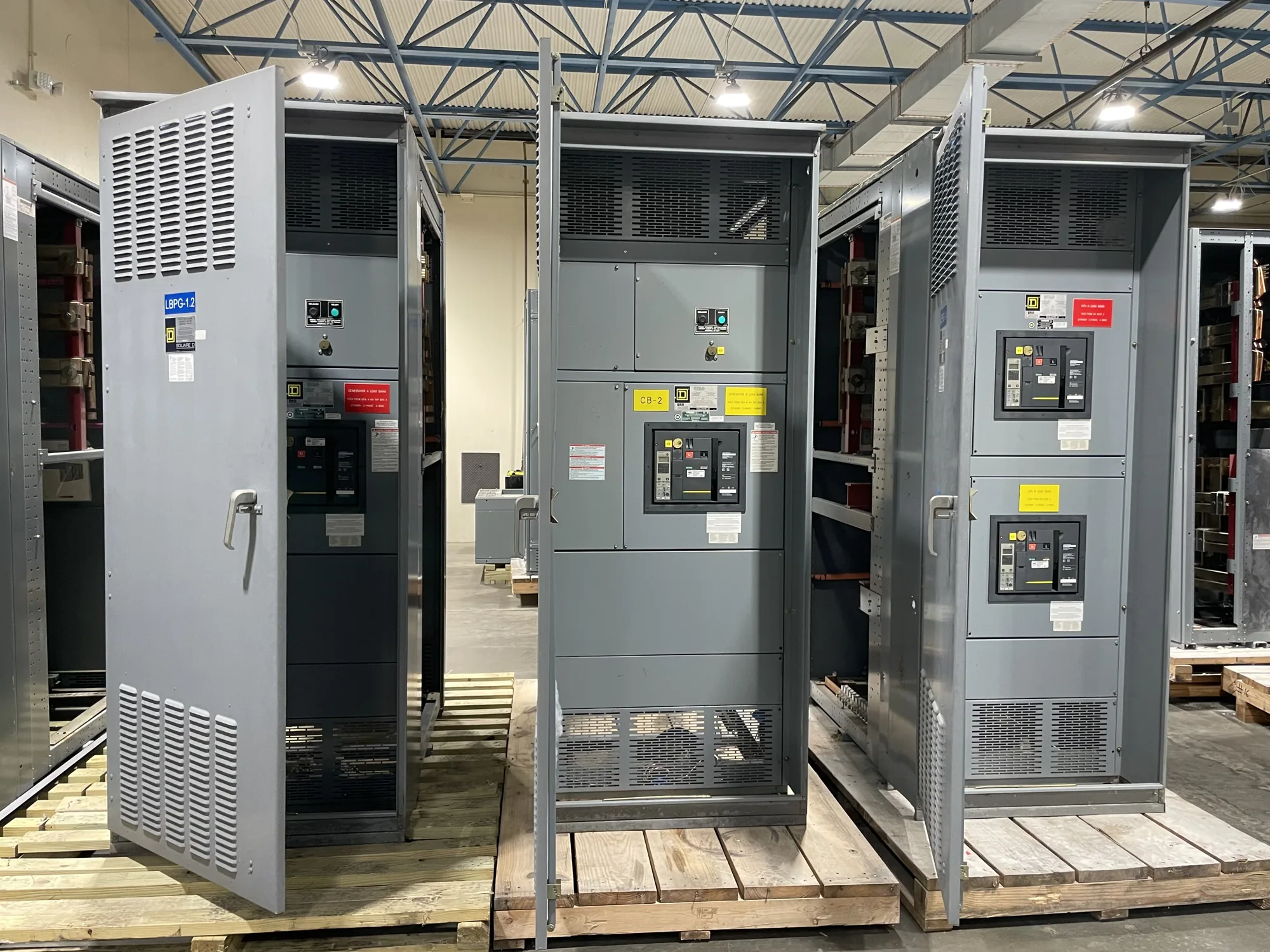
Where motor control centers fit in water and wastewater systems
Water and wastewater facilities bring together pumps, blowers, mixers, screens, conveyors, and other motor-driven equipment. A motor control center (MCC) groups motor branch circuits and associated control equipment in an assembly organized for the project. It is not simply another name for switchgear: its configuration is shaped by the motors and control functions it serves, while upstream distribution and protection remain part of the broader electrical design.
For a hypothetical treatment plant, one MCC might serve a group of process motors while separate equipment feeds other areas or loads. The actual division depends on the one-line diagram, operating strategy, space, and required isolation. Early coordination helps establish which motors belong in the assembly, where feeders originate, and how the MCC connects with process controls. These decisions can affect lineup arrangement, unit selection, cabling, and installation planning.
Match starters, drives, and protection to motor duties
Prepare a motor schedule that identifies each load, its electrical data, operating duty, and preferred control method. Across pumps and treatment equipment, motors may run continuously, start intermittently, or respond to changing process demand. The responsible engineer can determine whether a motor uses a starter, a variable frequency drive (VFD), or another specified arrangement. Starting method and operating profile influence branch-circuit design, control needs, and the heat produced within the assembly.
VFDs can support process control where variable speed is needed, but their application calls for more than selecting a drive by motor horsepower. Confirm the drive’s intended duty, operating range, enclosure and cooling requirements, and interfaces with the process control system. Review heat dissipation and spacing for the proposed lineup, especially where several drives operate together. The manufacturer needs the specified devices and arrangement to assess the configuration; project engineers determine suitability for the process and electrical system.
Feeder and motor branch protection must be coordinated with the system design and applicable project requirements. Provide motor full-load data, starting information when available, upstream protective-device details, and any specified coordination or fault-current criteria. Do not assume a standard unit arrangement will resolve protection or selective coordination. The engineer of record should define the required protection and confirm how the proposed assembly and upstream equipment work together.
Account for location, heat, and operating conditions
Indoor electrical rooms and remote or outdoor locations present different enclosure, access, and environmental questions. Document whether the equipment will be exposed to moisture, washdown, airborne contaminants, corrosive atmospheres, temperature extremes, or direct weather. Corrosion exposure should be addressed when present rather than presumed for every plant. The design team should specify the required environmental protection and materials for the actual site conditions, then confirm that the requested construction and equipment arrangement are compatible.
Room layout matters as much as the equipment outline. Share available dimensions, access routes, working clearances established by the project, cable entry preferences, and the location of nearby equipment. Discuss ventilation and heat removal where drives or other heat-producing devices are included. If the installation is remote, confirm how field wiring, communications, and operator access will be handled. These details support a manufacturable scope, but site preparation, installation, and field verification remain project responsibilities.
Resolve voltage and system details early
Do not specify an MCC using a voltage label alone. Provide nominal system voltage, system configuration, frequency, grounding arrangement, and the equipment maximum-voltage requirement if defined by the project. Distinguish the voltage available to the facility from the rating required for the assembly and its components. The responsible electrical engineer must confirm insulation and voltage requirements against the actual system; no universal assumption can substitute for the project’s design documents.
Also identify available fault-current information, upstream source and protective devices, and any project-specific withstand or coordination requirements. If these details are still being developed, state what is preliminary and who will confirm it. Changes to system configuration, source conditions, or motor data can affect equipment selection and drawings. A clear record of open items helps the buyer and manufacturer avoid treating an unverified assumption as a final design input.
Define controls and interfaces before release
List the signals and communication interfaces required between the MCC, plant control system, and field devices. Identify whether the scope calls for local operator controls, status and alarm points, interlocks, remote commands, or specified network interfaces. Provide control voltage and wiring conventions when established, along with applicable I/O schedules and sequence documents. The control system designer should define functional behavior; the MCC supplier needs the specified interface to configure the supplied equipment accurately.
Plan outage and cutover constraints with the project team. Existing facilities may have limited opportunities to interrupt pumping or treatment, but an MCC manufacturer cannot determine the plant’s safe operating plan. Share target milestones, drawing review expectations, shipping constraints, and site access limitations so procurement and installation planning can be coordinated. Availability and lead time depend on the order and must be confirmed; delivery dates should be established for the actual scope rather than assumed.
Prepare a purchase-ready scope
For a quotation, assemble the one-line diagram, motor schedule, voltage and system data, required starters and drives, protection criteria, environmental conditions, control interfaces, layout constraints, and project specifications. Note which information is final, pending, or subject to engineering confirmation. Include requested documentation, inspection or testing requirements, and any applicable listing requirements for review against the specific design. Do not presume that every assembly has the same listing, ratings, or test scope.
South Carolina Switchgear Builders manufactures new motor control centers to specification, with US-built equipment and all-American components, and ships nationwide. Confirm the proposed configuration, availability, applicable ratings, documentation, and delivery schedule against the project requirements before order release. Engineering decisions, installation, field testing, and maintenance belong to the responsible project professionals and qualified personnel using applicable safety procedures. A complete, coordinated scope gives the manufacturer a sound basis to quote equipment that fits the facility’s stated needs.