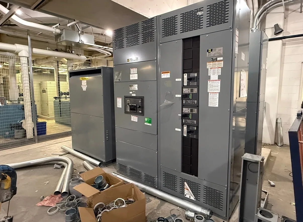
Where panelboards fit in a data center
In a data center, power distribution panelboards can serve as downstream equipment for distributing power to defined groups of branch circuits. Their role differs from that of switchgear: panelboards organize and protect branch-circuit distribution, while switchgear is a separate equipment category used for other distribution and switching functions. The project one-line diagram and equipment schedule should establish where each assembly belongs.
Consider a hypothetical facility with dense IT racks, cooling equipment, controls, lighting, and supporting loads. These loads may follow different distribution paths and operating priorities. Redundant sources or backup arrangements can further shape the design, but the panelboard configuration must follow the responsible engineer’s system design rather than assumptions based on facility type alone.
Translate IT and cooling loads into branch circuits
Start with the planned connected loads, circuit quantities, and expected growth by room, row, or other project-defined grouping. Rack power needs may change as deployments are phased, while cooling loads can have different equipment connections and operating patterns. The engineer should determine how these loads are divided among panels and circuits and identify spare capacity requirements without treating unused spaces as a substitute for a documented growth plan.
Branch-circuit count and protective-device requirements affect panel selection, physical arrangement, and coordination with upstream and downstream equipment. Buyers should provide the specified circuit schedule, device types, and any required provisions for future circuits. Confirm interrupting and withstand requirements, as applicable to the proposed equipment and system, against available fault-current information and the project’s coordination study. Do not select a fault rating by analogy to another facility.
Coordinate sources, redundancy, and monitoring
Where normal, standby, or other designated sources are part of the design, identify which source supplies each panel and how transfers or operating modes affect the distribution path. Redundancy strategies vary; two panels do not automatically establish independent power paths. The project team should confirm source relationships, upstream protective devices, transfer equipment interfaces, and any restrictions on shared components in the applicable design documents.
Monitoring needs also deserve early definition. Specify whether the project calls for metering, communications, alarms, or other monitoring provisions, and identify the required interface and data expectations. A panelboard’s physical space, device selection, wiring, and integration requirements can depend on these choices. Confirm who supplies and configures associated controls or monitoring components; do not assume that equipment supply includes facility-network integration or commissioning.
Resolve voltage and equipment ratings from project documents
Provide the nominal system voltage, phase and wire configuration, grounding arrangement, and source details stated by the electrical design. Distinguish the system’s nominal voltage from the equipment maximum voltage and insulation requirements where those values are specified. Voltage class alone does not establish a complete rating or prove that a particular panelboard is suitable for the application.
Also provide the available fault-current data, required protective-device characteristics, environmental conditions, and any project-specific construction or listing requirements. The responsible engineer should confirm that the selected equipment matches the one-line diagram and applicable project criteria. Ratings, standards, listing, and testing are design- and assembly-specific matters to verify for the offered configuration, not assumptions to carry over from a similar-looking product.
Plan placement, access, and maintainability
Panel location affects feeder routing, branch-circuit lengths, working access, and the practical separation of electrical spaces from IT or cooling areas. Share room layouts, equipment clearances, cable-entry preferences, and any constraints on wall space or access. The design team should resolve applicable access and safety requirements; a manufacturer’s equipment dimensions alone do not establish that a room layout is acceptable.
Consider how qualified personnel will identify circuits, inspect equipment, and carry out planned maintenance under the facility’s safety procedures. Clear schedules and consistent naming can help distinguish critical loads and distribution paths. If outages are constrained, explain the operating limitations and project sequencing needs early. Installation, field testing, maintenance, and energized work are not implied by equipment supply and must be handled by qualified personnel under applicable procedures.
Prepare a focused purchasing scope
For a useful quotation, provide the one-line diagram, panel schedules, voltage and system configuration, load and circuit requirements, specified ratings, fault-current information, enclosure and installation details, monitoring scope, and requested documentation. Include the expected project phases, required delivery window, shipping destination, and points of contact for technical questions. Identify open design decisions rather than silently converting assumptions into requirements.
South Carolina Switchgear Builders manufactures new equipment to specification, with US-built equipment, all-American components, and nationwide shipping. Availability and actual lead times depend on the order and require confirmation. The manufacturer’s scope is equipment supply; engineering approval, field installation, system integration, and commissioning should be assigned and coordinated separately by the project team.
Coordinate the panelboard with the full power path
Before release, compare the proposed panelboard scope with the latest approved electrical documents and confirm interfaces with feeders, upstream protection, transfer arrangements, and downstream loads. Resolve revisions to circuit counts, monitoring provisions, and future capacity before manufacturing details are finalized. A clear, coordinated specification gives the project team a sound basis for evaluating the equipment and planning its role in the data center’s distribution system.