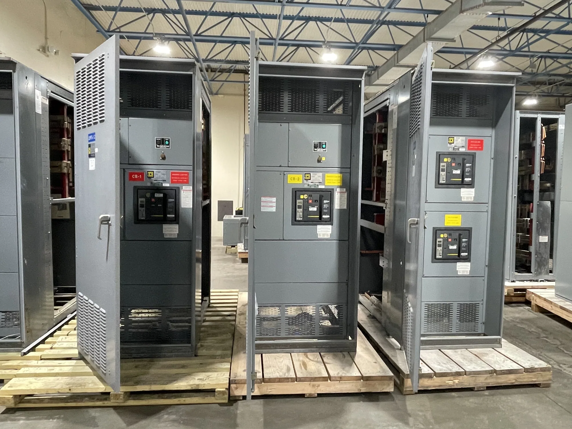
Panelboards serve branch-circuit distribution
A power distribution panelboard divides an incoming electrical supply among feeder or branch circuits serving downstream loads. It is a distinct equipment category from switchgear and switchboards, even though all may have a role in a facility’s electrical distribution system. Selecting the right category starts with the one-line diagram and the equipment’s intended function—not with a product name used casually in a project discussion.
Panelboards are commonly considered where a project needs organized branch-circuit protection and distribution at a defined location. The project engineer should confirm whether the required assembly is a panelboard, switchboard, switchgear, or another specified configuration. South Carolina Switchgear Builders manufactures and supplies new equipment, custom to specification, and ships nationwide. A panelboard’s availability, configuration, and suitability must be confirmed against the actual project requirements.
Start with voltage and system configuration
Document the nominal system voltage, phase, number of wires, grounding arrangement, and frequency as applicable to the design. The equipment’s voltage rating and maximum voltage must suit the system; do not assume that a familiar nominal voltage alone resolves compatibility. Insulation and device selection also depend on the specified system configuration. The responsible engineer should establish these requirements and confirm them for the proposed assembly.
Voltage is only one part of the selection. Identify the normal load current and expected connected loads, then establish required bus and branch-device current ratings. Account for applicable ambient temperature, enclosure conditions, loading patterns, and any derating requirements. A design that appears adequate by summing nameplate loads may still need engineering review for demand, diversity, continuous loading, or other project-specific conditions.
Size branch circuits and protective devices
Make a circuit schedule that identifies each load, its location, operating characteristics, and intended protective device. Include spare or future circuits only when the project team can define their purpose and required capacity. Circuit count, breaker arrangement, poles, and device types should follow the drawings and specifications rather than an assumed standard layout. The panel’s physical space and wiring approach should support the required circuits and maintainable installation.
Protective devices must be coordinated with the loads, conductors, and upstream distribution equipment as determined by the responsible electrical engineer. Confirm interrupting capability and the assembly’s short-circuit or fault-current requirements using available system information. The available fault current at the panel location and the required rating of the equipment are project-specific; they should not be inferred from voltage or from a generic product description.
Consider placement and operating environment
Panel location affects feeder routing, branch-circuit lengths, access, working space, exposure, and the practical organization of facility loads. Coordinate the proposed location with architectural and electrical plans, equipment access, and the owner’s maintenance approach. The project team should confirm enclosure type, environmental suitability, and any special construction needed for the installation. Do not assume a standard enclosure is appropriate for every room or process area.
For a facility with process motors, refrigeration, washdown areas, and packaging equipment, the distribution plan may call for panels serving different load groups or locations. That arrangement can affect circuit quantities, feeder routing, environmental requirements, and how equipment is isolated for maintenance. It is an example of a planning question, not a prescribed design: the engineer should determine whether one or multiple panels best fit the load layout and operating needs.
Evaluate trade-offs before finalizing the specification
More circuit spaces can provide flexibility, but a larger panel may affect footprint, feeder sizing, and placement. Conversely, a tightly constrained layout may leave limited capacity for later changes. Balance present loads and credible future needs against available space, installation constraints, and the cost and complexity of the overall distribution design. Clearly distinguish required circuits from optional provisions so the manufacturer can evaluate the intended scope.
Also reconcile the panelboard with upstream protective equipment and downstream loads. Confirm feeder conductors, overcurrent protection, grounding and bonding details, connection requirements, and any specified metering or accessories. These choices must agree with the one-line diagram and project documents. Listing, testing, ratings, and standards applicability depend on the actual design and supplied equipment and require confirmation; UL 891 applies to eligible low-voltage switchboards, not automatically to panelboards or all switchgear.
Prepare a useful request for quotation
Provide the latest one-line diagram, panel schedules, project specification, nominal voltage and system configuration, load information, required bus and branch-device ratings, and available fault-current data. Identify the installation environment, enclosure expectations, dimensions or space constraints, feeder and termination details, required accessories, and any project-specific documentation. Flag unanswered engineering items rather than substituting assumptions, and identify which drawings or revisions govern the request.
- State the quantity, required equipment category, and intended application.
- List circuit count, device requirements, spare provisions, and any defined future capacity.
- Provide ratings and standards requirements for confirmation against the specific assembly.
- Identify the project schedule and requested delivery window for availability review.
Coordinate engineering, supply, and installation
The owner establishes operating needs and project priorities; the engineer defines and approves electrical design requirements; and the electrical contractor coordinates installation details and field execution. The manufacturer can review the supplied specification and confirm the proposed equipment configuration, availability, and delivery timing for the order. The equipment is built in the United States with all-American components; confirm the applicable scope and configuration for the specific order.
Before release, resolve discrepancies among drawings, schedules, and specifications, and approve submittal details through the project’s normal review process. Confirm final ratings, construction, documentation, and delivery arrangements rather than relying on generic descriptions or assumed lead times. Installation, testing, and maintenance should be performed by qualified personnel following applicable safety procedures. A complete, coordinated specification gives the project team a sound basis for selecting new panelboard equipment that fits its distribution needs.