Start with the facility’s service and operating plan
For a distribution center or logistics facility, service-entrance switchgear is a central point in the incoming electrical service and the facility’s power distribution. Its configuration depends on the utility interface, the project’s electrical design, and the equipment and loads downstream. Conveyors, sorting systems, refrigeration, lighting, material-handling equipment, and charging infrastructure may all shape the project scope.
Build the equipment scope from the facility’s operating plan, not a generic warehouse load assumption. Identify which systems operate together, which are intermittent, and which may be added in later phases. A planned charging area or future automation line can affect feeder provisions and space planning, but those provisions should reflect an engineered load forecast rather than an assumed allowance. The responsible project engineer should establish the design basis.
Coordinate the utility interface and service disconnect
Confirm the service characteristics and point of connection with the utility and project team before settling the equipment arrangement. Relevant inputs may include the service voltage, available fault current, metering requirements, ownership boundaries, and the utility’s review or approval process. These details are project-specific; the manufacturer needs the approved design information and applicable utility requirements to evaluate a proposed assembly.
Clarify the service disconnect’s location, function, and relationship to downstream distribution. The one-line diagram should show the incoming conductors, main device, buses, feeder devices, metering or instrument provisions, and connections to other equipment. Access, working space, cable entry, room dimensions, and planned routes for conductors can constrain the physical layout. The electrical designer and installation team should resolve these interfaces before the final equipment arrangement is approved.
Grounding, bonding, and approval are design inputs
Grounding and bonding provisions should follow the project’s electrical design and the applicable requirements for the service and equipment. Provide the intended grounding arrangement, bonding points, neutral treatment where applicable, and any specified connection details for review. Do not assume a standard configuration is suitable: the responsible engineer must confirm how the service is grounded and how the equipment interfaces with the facility’s grounding system.
Identify which authorities and stakeholders review the design, including the utility and the relevant permitting or inspection parties. Provide the specifications that govern the assembly and clarify any required documentation, testing, or listing expectations. Applicability depends on the particular equipment and design; it should be verified against the supplied assembly rather than presumed. Early review can expose approval or interface questions while there is still time to coordinate design changes.
Size continuous current from real operating conditions
Continuous current selection starts with the calculated load and the project’s operating assumptions. Ask the engineer to document normal and maximum expected demand, diversity assumptions, charging schedules, conveyor duty, and any known simultaneous operating conditions. Distinguish expected operating current from short-duration or starting conditions, and provide the basis for each. The appropriate continuous current rating for the bus and devices must be confirmed for the complete specified design.
Do not select equipment by matching a single estimated load number. Bus and device ratings, enclosure conditions, ambient temperature, installation environment, and other design-specific factors may affect suitability. Ask whether any applicable derating conditions or temperature limits need to be considered, and have the responsible engineer establish the requirements. A future expansion plan should identify the added loads and timing clearly; reserved feeder space alone does not establish that the original service or bus capacity will support them.
Plan feeders and staged expansion deliberately
Warehouse projects often benefit from mapping feeders to actual operating areas or systems, such as conveyor zones, charging groups, mechanical equipment, and lighting distribution. The one-line diagram and feeder schedule should identify each load, its electrical requirements, protective-device needs, and intended point of connection. This helps the equipment team evaluate the required sections and provides a clearer basis for coordinating cable access, labeling, and maintenance isolation.
For staged construction, define what will be energized in each phase and what work must occur during planned outages. Reserve space only where the design team has also considered bus capacity, protection coordination, physical access, and future cable routing. Expansion should be treated as a planned engineering change, not an assumption that new equipment can be added without review. Installation, testing, and maintenance are work for qualified personnel following applicable safety procedures.
Prepare a useful equipment request
When requesting a quotation, provide the latest one-line diagram, load and feeder schedules, service information, applicable project specifications, and any utility or authority requirements already available. Include the desired equipment location, room and access constraints, cable-entry preferences, environmental conditions, and phase schedule. Identify the requested bus and device ratings only when established by the project design, and flag unresolved items for clarification rather than filling gaps with guesses.
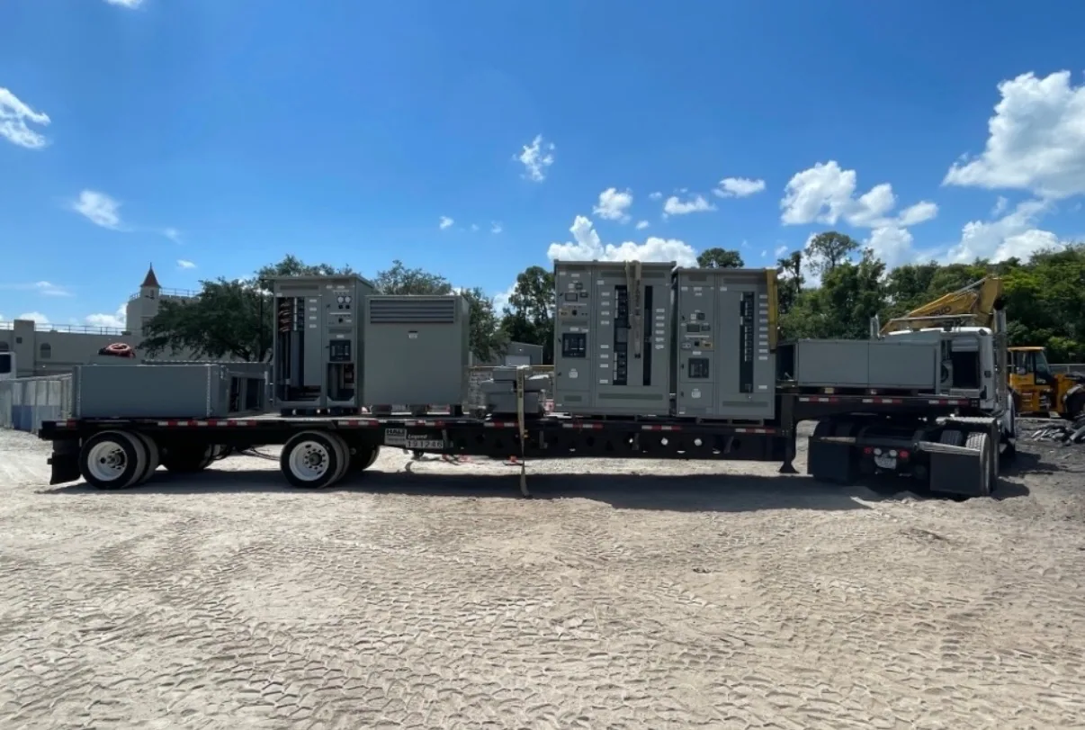
South Carolina Switchgear Builders manufactures new, custom-to-specification switchgear and switchboards, with US-built equipment, all-American components, and nationwide shipping. Availability and lead times depend on the order and must be confirmed; delivery dates, ratings, testing, and any applicable listing require confirmation for the specific assembly. Manufacturer supply is distinct from engineering, utility coordination, installation, and field services. A complete, coordinated scope gives the project team a sound basis to review configuration, resolve open questions, and move toward procurement.