Start with the distribution task
Switchboards and panelboards both receive electrical power and distribute it through protective devices, but they are typically used at different points and scales in a system. A switchboard may serve as a main distribution assembly or supply downstream equipment. A panelboard commonly serves a group of branch circuits or smaller distribution loads. Those descriptions are useful starting points, not substitutes for reviewing the one-line diagram and applicable equipment definitions.
The selection question is not simply which product is larger or less expensive. It is whether the equipment’s intended role, available protective devices, electrical ratings, construction, and installation constraints suit the project. Terminology can vary among project teams, so state the required function and configuration in the specification instead of relying on a product label alone.
How the distribution paths differ
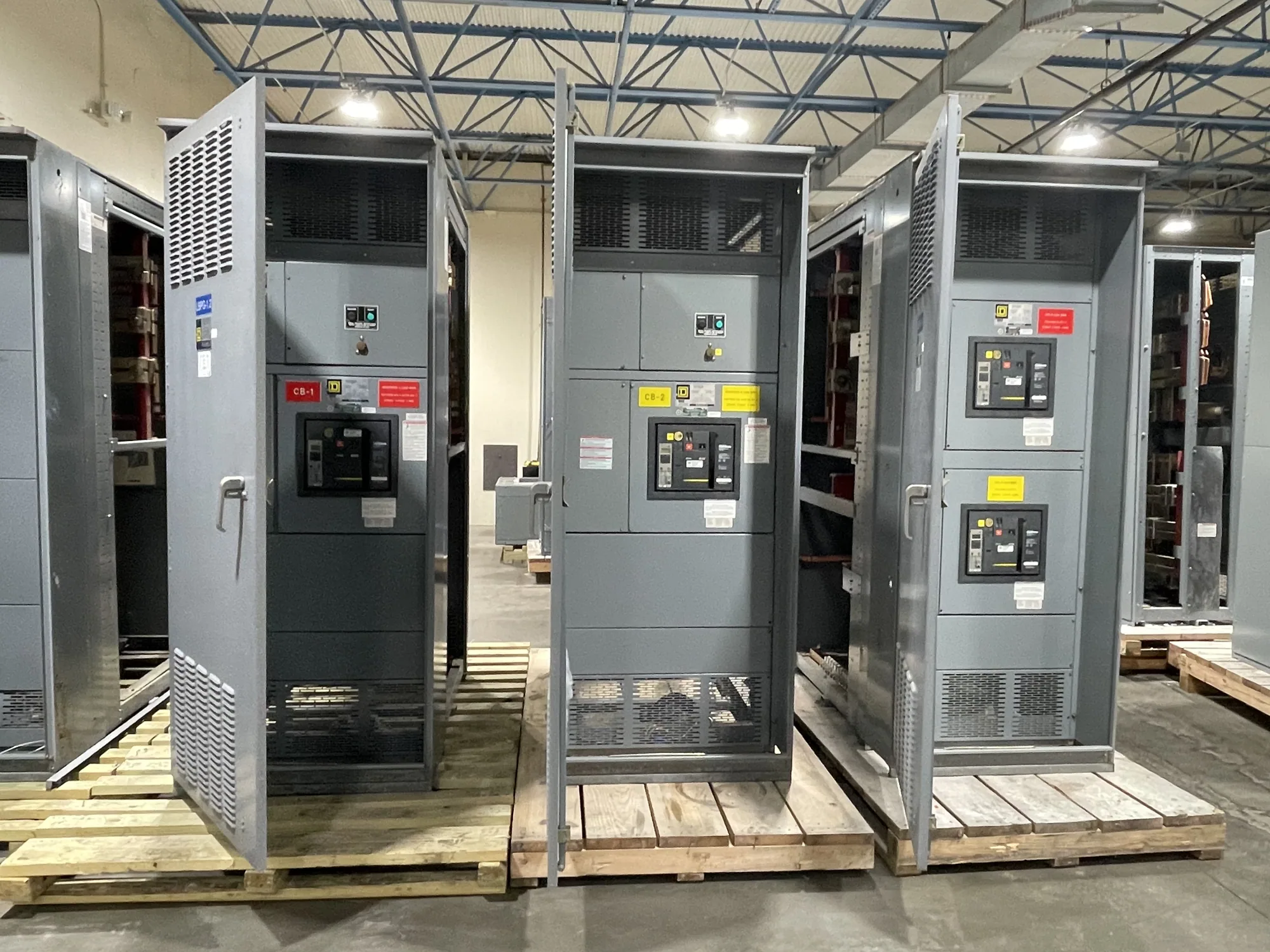
A switchboard arrangement may accommodate incoming service or feeder conductors and distribute power through multiple outgoing feeders. Depending on the design, those feeders can supply other distribution assemblies, equipment, or loads. The responsible engineer must establish the required source arrangement, protective-device types, bus configuration, and ratings. A switchboard is not automatically the right choice for every main distribution point, and its suitability depends on the documented system design.
A power distribution panelboard generally organizes protective devices for branch circuits or defined downstream loads in a panelboard format. Its circuit count, device types, voltage and current ratings, and physical layout must match the application. Where the project calls for larger feeders, a particular main-device arrangement, or a specific assembly form, confirm that the proposed panelboard design can meet those requirements rather than assuming it can replace a switchboard.
Compare the actual design constraints
Review the available electrical room or installation area, conductor entry and exit needs, working clearances, access for qualified personnel, and the route for delivering and positioning the assembly. Enclosure and environmental requirements also matter. Indoor and outdoor arrangements can differ in construction and installation details; the site conditions and project specification should determine the required design, not a broad assumption about either product category.
Electrical coordination is equally important. Ask the project engineer to define the system voltage, continuous load, expected fault conditions, protective-device functions, and coordination requirements. Confirm how future circuits or load growth should be handled, if that is part of the project. Do not infer interrupting capability, short-circuit ratings, or compatibility from the equipment name. Each rating and device selection must be verified against the actual system and proposed assembly.
Standards and assembly verification
Applicable standards depend on equipment type and the specific design. UL 891 applies to eligible low-voltage switchboards; whether it applies and whether a particular assembly is listed must be verified for that design. It should not be applied to medium-voltage switchgear, and it does not establish that every switchboard or panelboard meets the project’s requirements. Ask for the applicable standards and evidence relevant to the specified equipment.
Do not treat switchboards, panelboards, and switchgear as interchangeable terms in drawings or procurement documents. Identify the product type and intended function, then confirm ratings, construction, listing applicability, testing requirements, and other compliance details for the specific assembly. The project team should resolve any gaps between the one-line diagram, equipment schedule, specification, and supplier submittal before approving a configuration.
A practical decision comparison
Consider a building distribution plan with one assembly feeding several downstream areas, each of which requires its own branch-circuit distribution. A switchboard could be considered for the feeder-distribution role, while panelboards could be considered closer to the grouped branch loads. That is an illustrative arrangement, not a universal recommendation. The engineer must confirm load calculations, protection, ratings, layout, and code requirements for the actual project.
- If the principal need is organizing multiple outgoing feeders, define the feeder count, destinations, protective devices, and incoming arrangement for evaluation.
- If the principal need is branch-circuit distribution, define the circuit count, device requirements, load groups, and space constraints.
- If the boundary between feeder and branch distribution is unclear, resolve it on the one-line diagram before choosing equipment.
- If the specification names one product type but describes another function, request clarification rather than silently substituting equipment.
Information to prepare for a manufacturer
For a useful equipment review, provide the one-line diagram, equipment schedule, project specification, and available fault-current or system study information when applicable. Include voltage, phase, frequency, load data, incoming and outgoing conductor requirements, protective-device details, enclosure and installation conditions, and any required control or metering features. Identify the governing standards and any project-specific listing or testing requirements for confirmation.
Also communicate the project location, delivery constraints, required submittal information, and anticipated decision and installation milestones. South Carolina Switchgear Builders manufactures new switchboards and power distribution equipment to specification, with US-built equipment, all-American components, and nationwide shipping. Availability and actual lead times depend on the order and must be confirmed; provide the project schedule early so feasibility can be reviewed rather than assumed.
Make the decision through documented fit
A sound choice follows the system function and verified design, not a general ranking of switchboards over panelboards. Have the responsible engineer establish where feeder distribution ends and branch distribution begins, then compare proposed equipment against the electrical and physical requirements. Confirm ratings, standards, construction, delivery details, and any project-specific testing or listing before release for manufacture.
When the drawings and specification agree on the intended function and required features, the manufacturer can evaluate a defined scope and identify questions that need resolution. That process helps avoid confusing product categories, late design changes, or assumptions about performance. Final equipment selection should be documented in the project design and purchasing records, with installation and verification assigned to qualified personnel following applicable procedures.