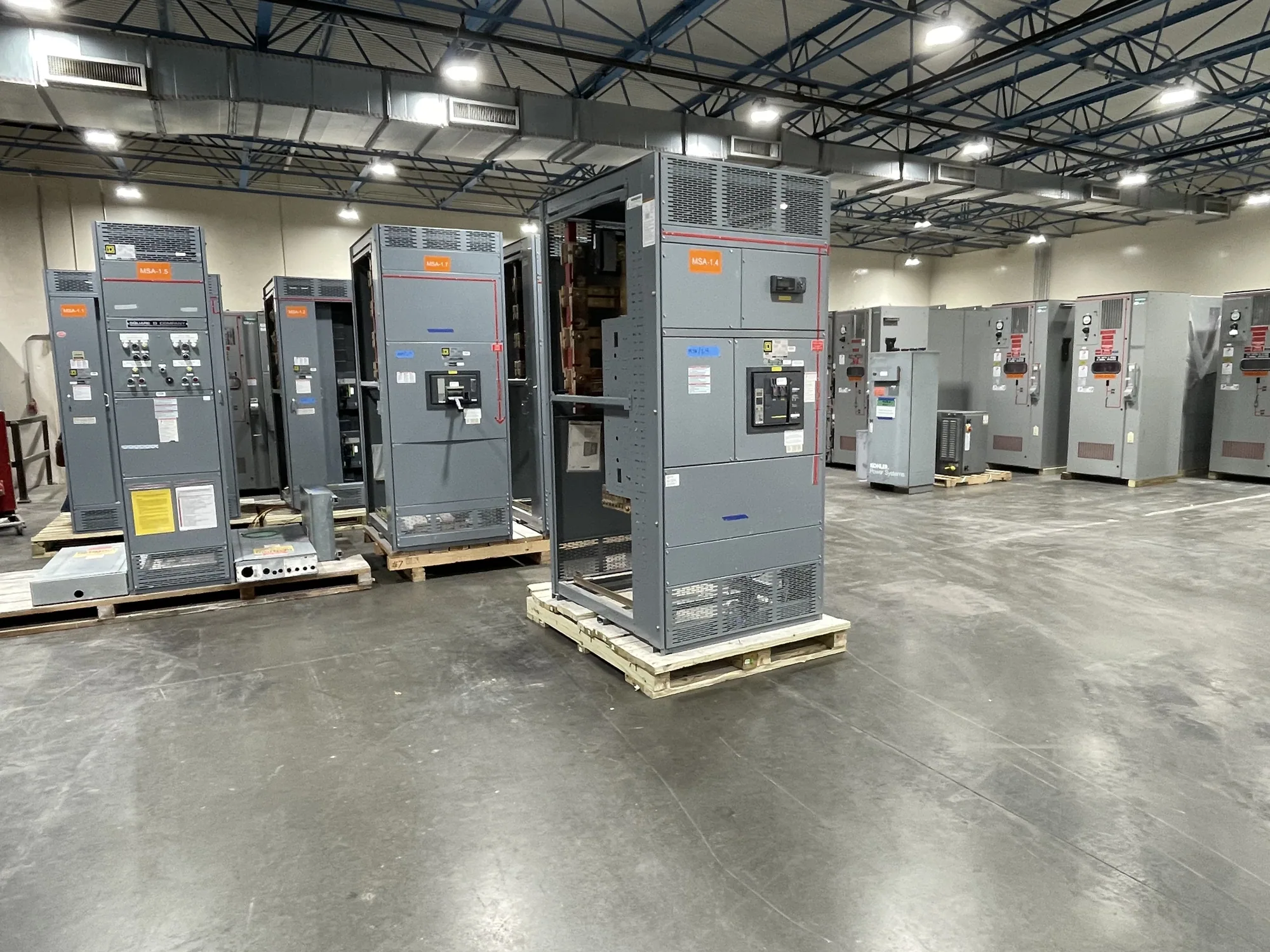
Start with the drive and the motor-control lineup
Variable-frequency drives (VFDs) change how a motor receives power, so their inclusion affects more than the motor starter selection. A motor control center (MCC) specification may need to address drive size and type, feeder protection, enclosure arrangement, ventilation or cooling, controls, communications and coordination with the upstream electrical system. The details depend on the particular drive, motor, operating profile and site.
Begin by identifying which motors will use drives and whether the drives are to be installed in MCC units, in a separate enclosure, or elsewhere in the electrical distribution system. This is a design decision, not a universal rule. The responsible engineer should confirm the proposed arrangement against equipment documentation, project requirements, maintenance access and environmental conditions. Provide the manufacturer with the intended configuration so the lineup can be designed to the actual scope.
Heat and physical arrangement require project data
Drives generate heat during operation, and that heat can affect the temperature conditions inside an MCC enclosure. The specification should identify the drive model or its documented heat-loss information, expected operating conditions, enclosure arrangement and any constraints on room temperature or ventilation. Do not assume that a standard lineup configuration will suit every combination of drives or operating duty.
Review how heat will be managed in the proposed installation. Depending on the equipment and site, the engineer may need to assess ventilation, cooling provisions, spacing, enclosure design or separation of drive sections. The acceptable approach must be confirmed for the specific assembly and its surroundings. Provide ambient conditions, altitude where relevant, indoor or outdoor location, contamination concerns and other site information requested by the design team. These factors can influence equipment selection and layout.
Harmonics and upstream system coordination
VFDs can affect current waveforms, so their impact on the electrical system should be reviewed using the actual drive information and project conditions. The specification should identify the drives’ input characteristics and any proposed harmonic mitigation or filtering, if applicable. The responsible electrical engineer must evaluate the installation in context, including the source system and other nonlinear loads; a generic statement that drives will or will not cause a problem is not a substitute for that review.
Ask what system information the project engineer needs to complete the assessment, and provide the selected drive documentation rather than relying on a preliminary nameplate estimate alone. If mitigation equipment is contemplated, clarify whether it is included in the MCC scope, provided separately, or still under evaluation. Its physical space, heat contribution, connections and coordination requirements may affect the lineup. Any design-dependent performance expectations need to be documented and verified for the specified arrangement.
Controls, communications and protection
Describe how each drive is expected to start, stop and respond to process commands. The MCC specification can identify local operator devices, remote signals, interlocks, fault indications and control-power expectations, but the project team must define the actual interface. Where a control system or network is involved, specify the intended protocol and division of responsibility. Confirm which signals and communications features the selected drive supports.
Protection and coordination also need review. Identify motor data, drive input requirements, feeder and upstream protective-device expectations, and any required operating or fault responses. The engineer should confirm compatible components and settings for the particular design. Do not assume that drive protection replaces every upstream or motor-side protection function, or that one arrangement applies to all motor loads. Clearly distinguish project requirements from features that remain subject to engineering confirmation.
Use the real operating scenario, not a generic example
Consider a project with several pumps, where some motors may run at reduced speed and others operate across a different duty range. The number and size of drives alone do not determine the MCC design. The engineer also needs the motor characteristics, expected operating pattern, simultaneous operation, control method, site conditions and selected drive documentation. Those inputs help establish the lineup arrangement and identify questions about heat, system effects and interface requirements.
A common misunderstanding is that specifying a VFD automatically dictates a particular MCC rating or enclosure solution. It does not. Continuous-current requirements, temperature conditions and equipment ratings must be determined for the actual assembly and application. Another frequent gap is treating drive data as final before the motor or control scheme has been selected. Mark preliminary assumptions clearly, then update the specification when submittal information is available.
Information to assemble before requesting a proposal
For a useful review, provide a motor and load schedule, motor nameplate data when available, drive selections or required characteristics, quantity of each unit and expected operating duty. Include the one-line diagram or a clear description of the source and feeder arrangement, control narratives, interface requirements, and any known harmonic-study criteria. State the required MCC configuration and identify equipment that is in or out of the manufacturer’s scope.
Also document installation conditions, including location, ambient temperature range, enclosure needs, available space, access constraints and project schedule. Ask the manufacturer to identify information still needed, proposed assumptions, configuration limits and any ratings or listing details requiring confirmation for the specific design. Availability and lead times depend on the order and must be confirmed. Clear, current inputs make it easier to evaluate a new, custom-to-specification MCC and coordinate it with the wider project.
Coordinate decisions before design is finalized
Before releasing the specification, have the project engineer, drive supplier and MCC manufacturer resolve open questions about heat management, harmonic review, controls, protection, layout and responsibility boundaries. Confirm continuous-current and environmental requirements against the project documents, and reconcile the final equipment data with the approved design. Installation, testing and maintenance should be performed by qualified personnel using applicable safety procedures. This coordinated review keeps the MCC specification tied to the actual drives and operating conditions rather than assumptions.