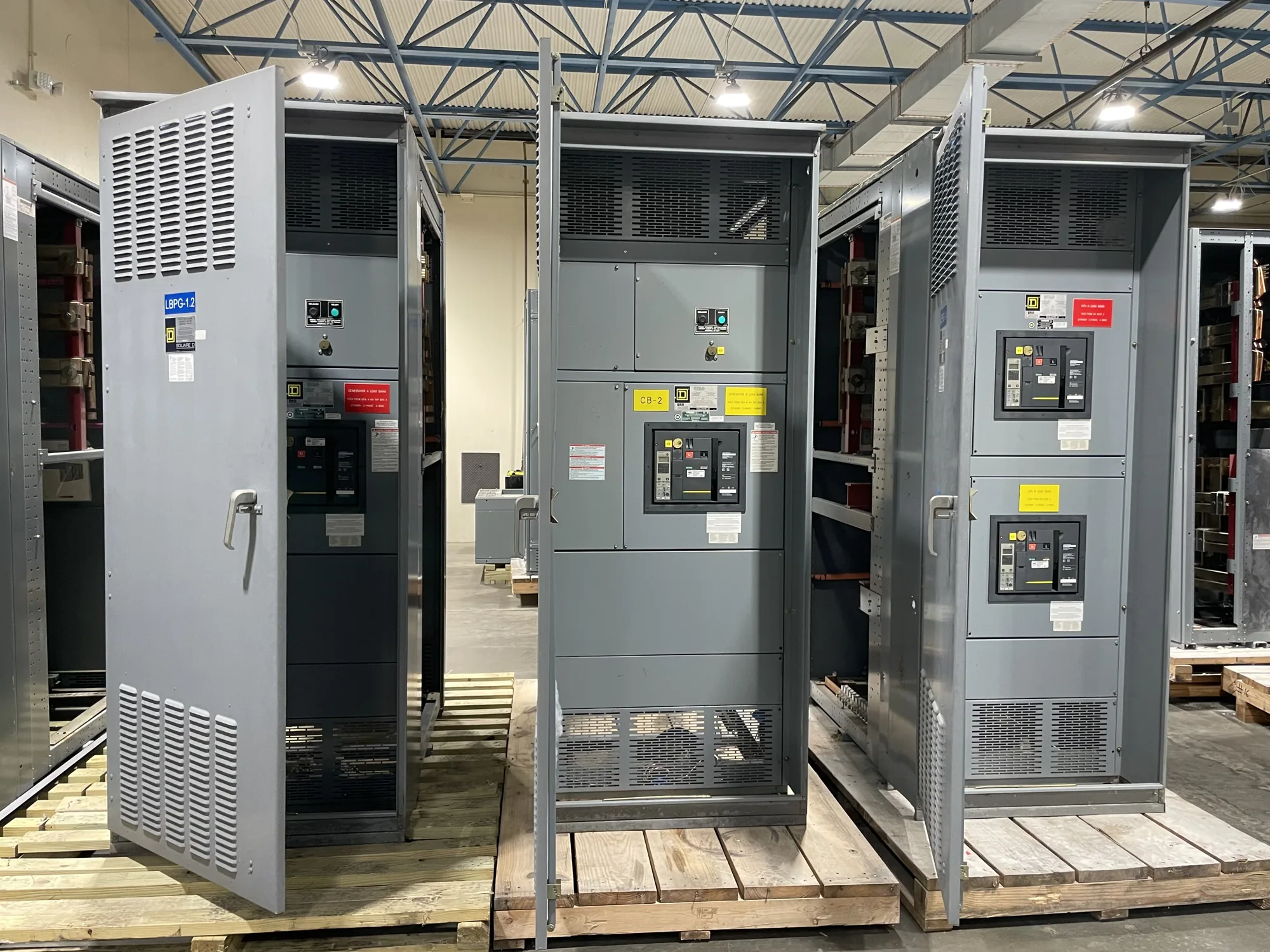
Start with a short-circuit study
Available fault current is determined by analyzing how much current the electrical system could deliver to a fault at a particular point under defined operating conditions. A qualified electrical engineer or other responsible design professional develops the short-circuit study from source and distribution-system data. It is not a value that can be selected reliably from a building’s size, service voltage, or a general equipment catalog.
The study calculates fault current at relevant buses and equipment locations, accounting for the impedance between the source and each point. Results depend on the system configuration and assumptions used, so the engineer identifies the operating cases being evaluated. The study should support equipment selection and coordination with the project’s drawings and specifications; the manufacturer needs those project requirements to configure new equipment appropriately.
Utility source data sets the starting point
For a utility-connected service, the utility’s available fault-current information at the service point is a key input. The project team should obtain the applicable utility data for the planned service voltage and connection, and confirm its basis and date with the utility and engineer. Source strength can vary with the supply arrangement and system changes. A prior project’s value or a generic utility estimate should not be assumed to represent this service.
Where the service includes an on-site generator, parallel source, or other source that can contribute current, the engineer evaluates its contribution and operating scenarios as appropriate. Whether sources operate together, separately, or through transfer equipment can change the cases that matter. The project documents should make the intended operating arrangements clear rather than treating every source as permanently connected or assuming that only the utility contributes.
Transformers, conductors and configuration matter
Transformer data affects the current that can pass from the source into downstream equipment. Relevant information may include transformer rating, impedance, voltage, connection, and the number of units operating in parallel. The engineer verifies the actual or specified data and considers how the transformer is connected to the system. Changing transformer impedance or adding parallel capacity may change calculated fault current, so preliminary assumptions need confirmation before equipment ratings are finalized.
Between the source and a point of interest, conductors, busway, cables, and other system components add impedance. Their material, size, length, and arrangement can affect the calculated result. One-line diagrams, equipment schedules, and conductor information help the engineer model the path accurately. Switchboard or switchgear lineup arrangement, tie-breaker position, and normal versus alternate feeds can also define distinct configurations to study, depending on the design.
Understand the result at the equipment location
Consider a project with a utility service feeding a transformer and two distribution sections connected by a tie. The engineer may need to evaluate the sections with the tie open and, if the design permits, with it closed. Those arrangements can produce different source paths and fault-current results. This is an illustration, not a rating recommendation: the engineer must use the actual utility, transformer, conductor, and equipment data for the project.
Available fault current is not interchangeable with every short-circuit rating on an equipment submittal. The responsible engineer compares the calculated duty at the connection point with applicable equipment ratings and the specified protection scheme. The team must distinguish equipment interrupting capability from short-time or withstand capability where those ratings apply. Do not infer that an assembly is suitable simply because one rating number appears higher; the specific rating basis and application require review.
Coordinate protection and equipment selection
Protective devices influence how a system responds to faults, but relay settings do not replace determining the available current. The study and protection review should use consistent system data and account for the selected devices and intended operating modes. The engineer determines the appropriate protection and coordination approach. For equipment procurement, provide the manufacturer with the required ratings and configuration rather than asking the manufacturer to infer a complete system study from incomplete service details.
When requesting new switchgear or a switchboard, identify the project voltage class, service arrangement, bus and feeder configuration, source and transformer information, and the fault-current results and rating requirements established by the design team. Include relevant one-line diagrams and specifications, and flag unresolved utility data or alternate operating cases. Clear inputs help the manufacturer assess the requested design; availability, delivery timing, ratings, listing, and testing details must be confirmed for the actual equipment and order.
Questions to resolve before finalizing an RFQ
- What utility-provided fault-current information applies at the service point, and what system conditions does it represent?
- Which transformer and conductor data are confirmed, and which remain preliminary?
- What normal, alternate, or tie-breaker configurations must the study evaluate?
- At which equipment locations are fault-current results needed, and what ratings does the engineer specify there?
- Are generator or other on-site sources included, and which combinations of sources are permitted to operate?
- Who is responsible for updating the study if utility, transformer, or system configuration data changes?
Resolve these questions with the project engineer and utility before treating a calculated value as final. If a material input changes, ask the responsible engineer to determine whether the study and equipment requirements need revision. South Carolina Switchgear Builders can use confirmed project specifications to discuss a new, custom-to-specification equipment order. Actual design details, availability, and lead time depend on the order and require confirmation before procurement.