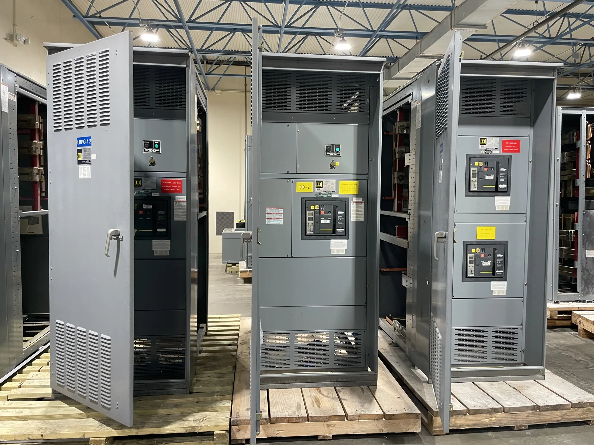
The direct answer: not in every assembly
No. Neutral and ground should not be bonded inside every distribution assembly by default. The proper bonding point depends on the system configuration and where the assembly sits in the service or distribution arrangement. A bond in the wrong location can create unintended current paths on conductive equipment and grounding conductors. The project engineer must establish the intended arrangement and specify it for the particular installation.
In this context, “neutral” generally refers to the grounded circuit conductor, while “ground” may mean the equipment-grounding conductors and bonded metal parts. Those terms describe different functions, even though they are connected at a defined point in many systems. A distribution assembly’s internal bus layout, bonding provisions, and incoming conductors must match the approved design; the words “main” or “distribution” alone do not settle the question.
Why the service arrangement matters
For service equipment, the neutral-to-ground bond is commonly associated with the service disconnecting means, subject to the actual system and applicable code requirements. Downstream distribution equipment generally has a different role: neutral and equipment-grounding paths are kept separate where the design requires it. However, this is not a universal rule that can be applied without knowing the source, disconnects, system conductors, and equipment function.
Consider a facility receiving power through service-entrance switchgear, followed by a separate distribution assembly. The engineer must determine which equipment is the service disconnecting means and where the system bonding point belongs. Bonding the downstream assembly merely because it contains a neutral bus could create an additional bond. Conversely, omitting a bond where the design requires one is also a serious design error. The correct result follows from the documented system, not a generic product label.
Understand the electrical and safety tradeoffs
A correctly designed bonding arrangement supports an effective fault-current path so protective devices can respond as intended. An unintended additional neutral-to-ground connection can allow normal neutral current to flow on metal enclosures, raceways, or equipment-grounding conductors. That may introduce objectionable current and complicate troubleshooting. These outcomes depend on the installation; they are reasons to verify the design, not claims that a particular assembly will behave the same in every system.
Another common misunderstanding is that grounding and bonding are interchangeable terms, or that a ground bus should always be connected to a neutral bus inside each enclosure. Equipment grounding bonds exposed conductive parts into the grounding path, while the neutral carries current as part of the circuit in applicable systems. The engineer should identify each conductor and connection point explicitly. Do not infer the intended bond from a bus’s appearance or from a drawing that omits system context.
Information the design team should confirm
Before specifying a new assembly, provide the manufacturer with the one-line diagram and identify the service point, source, upstream and downstream disconnects, and the assembly’s intended function. State whether a neutral is required, how incoming and outgoing conductors are arranged, and where the engineer intends the system bonding jumper or other bonding connection. Include project voltage class and relevant equipment ratings, but have the responsible engineer establish those values from the actual system.
Ask the engineer to confirm the applicable code edition and any authority having jurisdiction requirements for the installation. The manufacturer can review the specified assembly configuration and identify information needed to build it, but should not be expected to determine an undocumented service arrangement. Confirm that neutral and ground bus provisions, bonding hardware, conductor terminations, and any isolation requirements are shown consistently in the drawings and equipment specification.
Questions to resolve before release
Useful questions include: Which assembly is the service equipment? Where is the intended neutral-to-ground bond? Does this lineup contain a neutral, and is it required to be isolated from the enclosure and equipment-grounding bus? What upstream equipment establishes the source and bonding point? Are there separately derived sources or alternate operating arrangements that change the design? The project engineer should answer these based on the actual system rather than on a general rule.
Also ask how the design will be documented for review and installation. Check that the one-line diagram, grounding details, equipment schedule, and manufacturer submittal agree. If the drawings change, revisit the bonding instructions before the assembly is released. Applicable listing and standards questions must be confirmed for the specific equipment and design; no single standard or general product description resolves every grounding decision.
Coordinate the assembly with the project
When requesting a manufacturer quotation, provide the current specification, one-line diagram, required neutral and grounding bus details, and the designated service or distribution role. Flag unresolved questions rather than allowing assumptions to become build instructions. Confirm the final configuration, applicable ratings, standards, and delivery schedule against the project documents. Availability and lead time depend on the order and require confirmation.
For a new custom distribution assembly, clear bonding instructions help align engineering documents, equipment construction, and site installation. Have the responsible engineer approve the system arrangement, and have qualified personnel perform installation, testing, and maintenance under applicable safety procedures. If the project cannot identify one intentional bonding point and explain its relationship to the service arrangement, resolve that issue before equipment release.